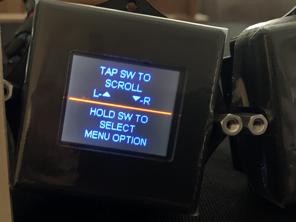
In Part 1 of this update, we showed the process of having custom gauges made by our friends at Dakota Digital. The gauge set is the HDX-2070, and part of the set includes a TFT (thin film transistor) message center that can display other information, all customizable by the user. Instead of the standard set of six gauges – like our previous VHX-1060 – the HDX-2070 includes a seventh gauge that houses the TFT message center.
For our Belvedere, however, that seventh gauge won’t fit in the confines of our OE cluster housing, and it would look a little odd to have it mounted elsewhere on the dash. So we were back to seeking some ideas from our friends at Dakota Digital to help us with a solution. Fortunately, they also offer to mount the TFT display in a few different configurations – including a matched pair of smaller displays that retrieve the same data as the larger gauge, but splits the information into two, smaller formats.
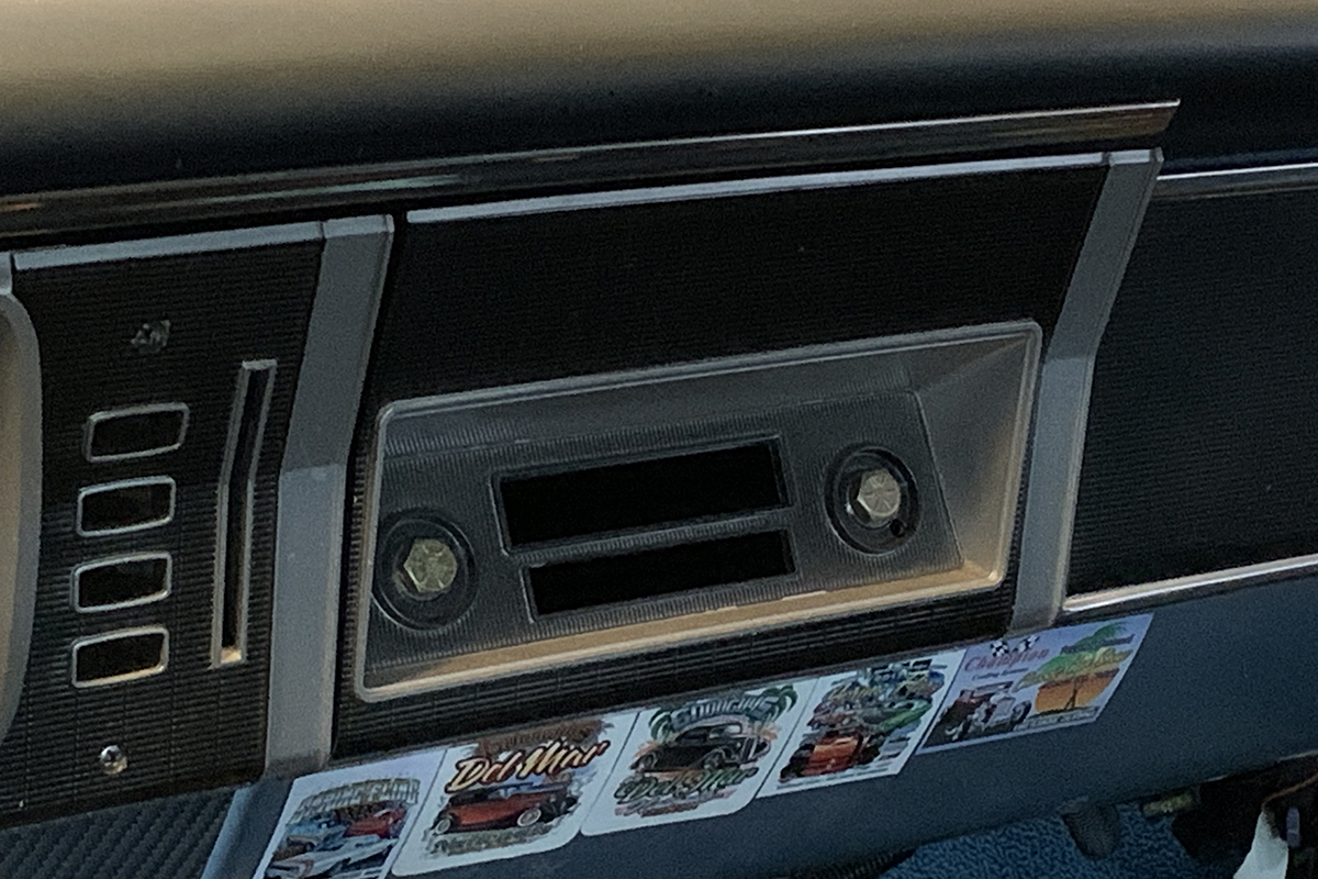
Since we had already decided on a double-DIN stereo mounted in the console, that left the factory radio location open for our TFT displays, and all we had to do was figure out a way to mount them from behind, without cutting up the dash and the factory radio faceplate beyond recognition. The goal was to keep that original radio faceplate, but to upgrade it to display our two small message centers. It was time to get creative, and for that, we once again called on the help of our AlgoLaser Delta to fabricate some mounting brackets out of wood.
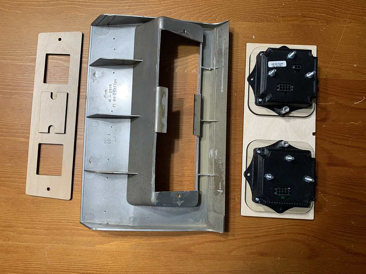
The first part of the job was to get measurements, and we had to pay particularly close attention to the fact that the display screen is not symmetrical with the housing, meaning, it’s slightly off-center. That meant that we had to make sure how we mounted them, and to design the setup slightly offset so that the two TFT displays are spaced equally in the opening on our dash. With all of the measurements recorded, it was time to design the mounting system in CorelDraw, then to send the file to the laser for cutting.
While most of us are familiar with a lot of plastic in dashboards, there were quite a few cars back in the 1960s and earlier that had actual wood paneling on the dash, and that’s where the idea came up to use wood as a mounting system; that, plus the fact that it was much easier to cut wood with the laser than to try to cut ABS with a jigsaw and a Dremel tool. ABS can’t be cut easily with a diode laser, and aside from the difficulty it also emits hydrogen cyanide, which is very toxic to humans. Wood, on the other hand, cuts and engraves well.
Since our original radio faceplate had been left intact, that gave us some ideas for mounting the entire component. The original radio was the only means for attaching the black and silver faceplate, and without the radio in the dash, there was no way to attach it. So we devised a plan to use longer screws and barrel nuts mounted on the TFT displays, then much like the HDX-2070 mounting system, we sandwiched the dash between the faceplate and the pair of displays to hold them securely in place.
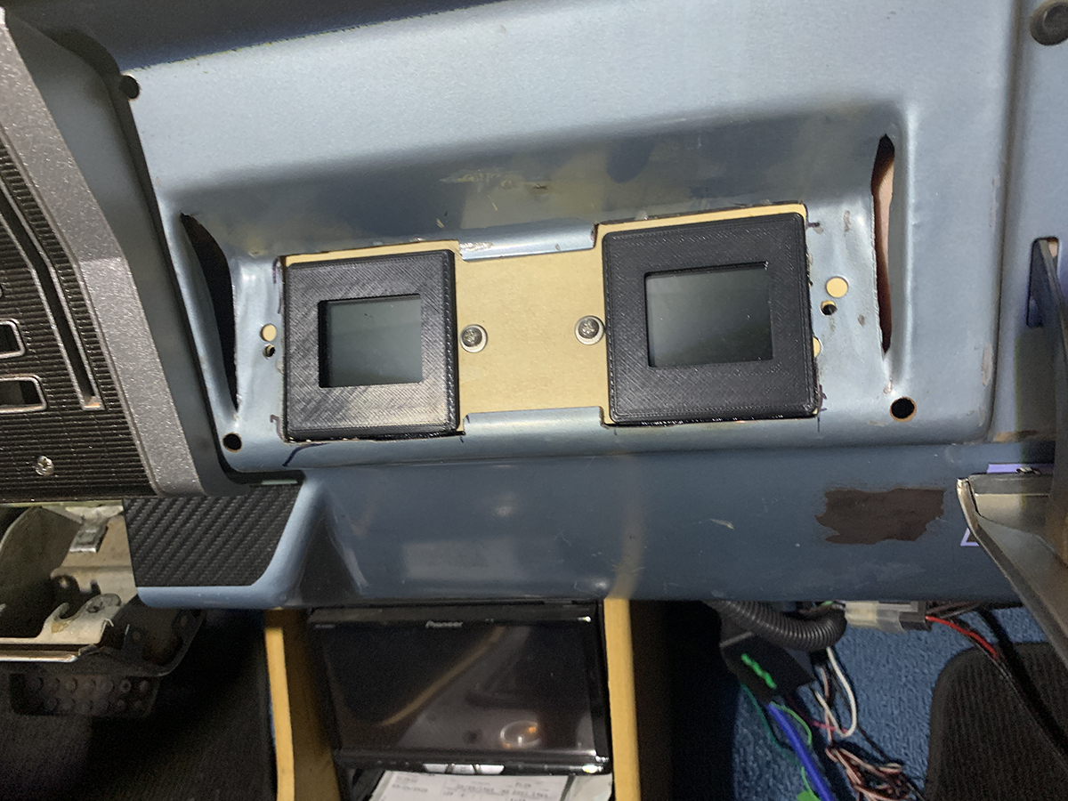
We had to cut out the bottom portion of the mounting panel, and that also meant devising a different spacer system to put it all together. So we used a stronger 1/4″ hardwood for the support, and pieced it together and made a couple of small cuts in the metal dash, allowing the TFT display housings to protrude through to the surface, and made another test fit to see if it would work.
At this stage of the build, we’re already knee-deep into our restomod, and there’s no going back on getting this car to its original state. We’ve welded frame connectors, added mini tubs, and welded up the support for the four-link coil over rearend, and now the dash has been cut into and that means we’re officially a restomod. It reminds me of one of my favorite quotes from my friend Mike Ring, of Ringbrothers. I had asked him about how he responds to those who accuse the duo of “destroying a perfectly good car” when they complete a custom build. He told me, “We don’t do restorations. Restorations are all about what’s wrong with a build, restomods are all about what’s right with them.” Profound words.
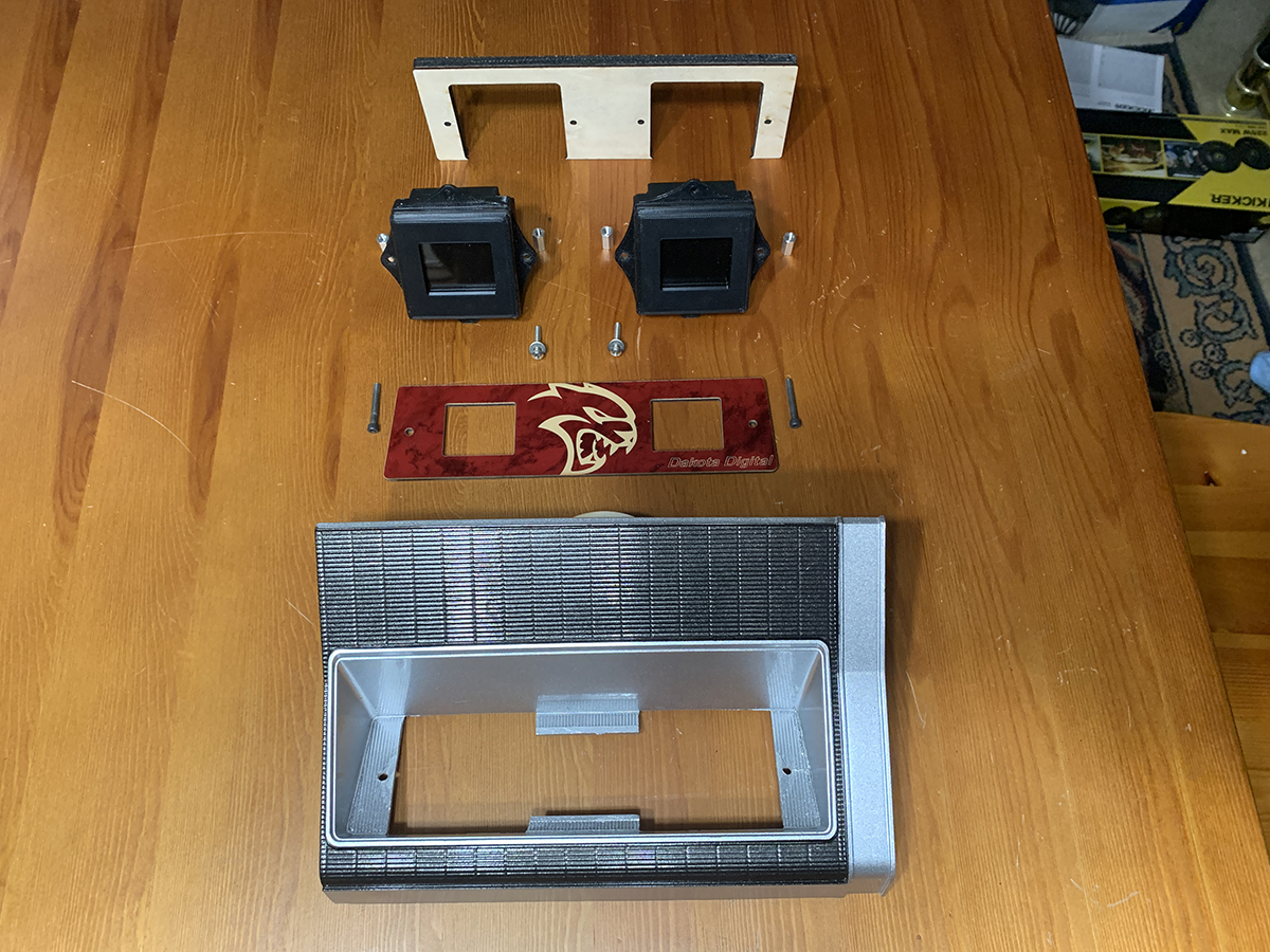
After cutting into the sheetmetal of the dash, the next bit of trimming was another one of those modifications that has purists cringing: cutting into the original radio faceplate with a Dremel tool. The faceplate was designed to add some detail to the otherwise boring AM radio that came in the car, and these faceplates are not easy to find anymore; they also command a pretty penny if you want one that is in better-than-driver condition.
We cut apart the center, measuring carefully before we started cutting. Though we were planning to mount a new faceplate to match the instrument cluster, we still wanted to have some support behind it to hold the components together without them moving around easily. The display screens are rather small, but the housings with all of the electronics and control boards were slightly larger, but they fit well behind the dash and it turned out to be a decent display.
In a perfect world with thousands of dollars worth of tools, the entire dash could have been done to show quality, without any minor flaws that are inherent to a home build such as this. But this car is a driver, with hopes to be back out at Willow Springs with the new drivetrain soon – if it’s still open for racing by the time we get done. We never bought this car for trophies or awards, we bought it to drive – and to build it the way we wanted to, and we’re achieving that mission as we progress along.
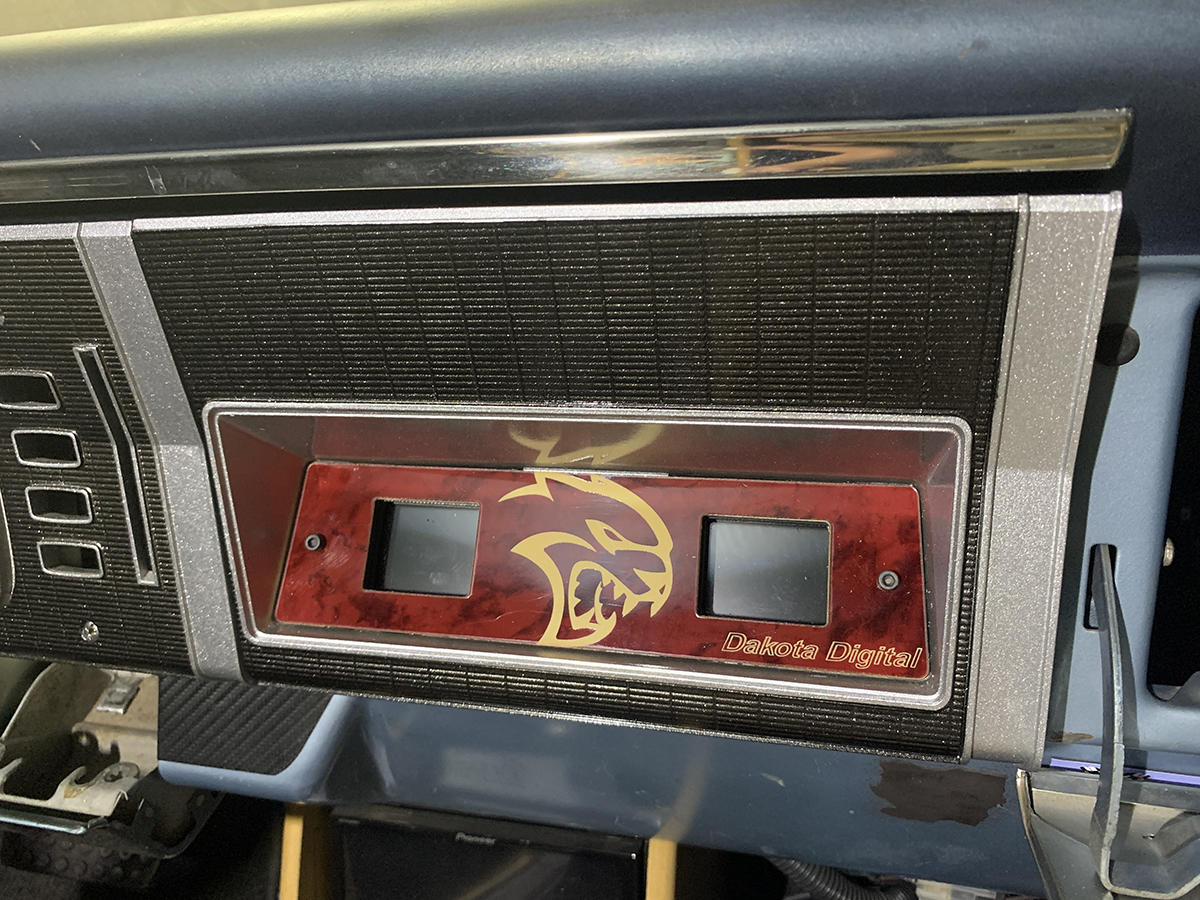
The first time we mounted the displays we used Allen head bolts, but in keeping with the them on the rest of the dash where it’s mixing original components with modern electronics, we opted for a pair of stainless steel pan head Phillips screws to hold it in place, just to give it that final touch.
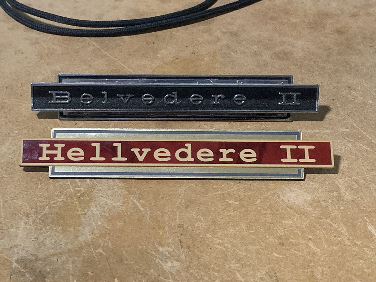
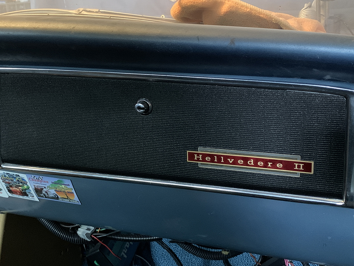
After bolting all of the components in place, there was one more part of the dash that needed some updating, and that was the glovebox door. The emblem on the glovebox stated, “Belvedere II” and we needed to update that as well, to math the them of the car. So it was back to making measurements and recreating the emblem in CorelDraw, then hitting up the laser one more time for the new – and improved – glovebox emblem.