 A couple of decades ago, it was popular to simply add a switch under the dash to control an electric cooling fan, often referred to as an auxiliary fan. This was a mediocre way of doing things, primarily because the current required to spin the fan was drawn through the switch itself. In electrical terms, that’s a no-no; you should never rely on a switch on the dash to handle the kind of current required to power an accessory that is more than 10-15 amps.
A number of things can (and sometimes will) go wrong, even if you buy a switch that can handle 15 amps. The other drawback was that this method required your attention to make sure you flipped the switch – especially if you replaced your mechanical fan altogether.
Those mechanical fans were fine for stock vehicles coming off the showroom floor in the 1960s and 1970s, but back then many cars were seeing horsepower numbers far below 400. Today, it’s common to see a 500+ horsepower car or truck used as a regular – or even daily – driver.
Using a mechanical fan for a high horsepower application can work just fine if a couple of things are considered. A larger radiator, a larger clutch-fan, and a shroud would probably keep your engine cool; mechanical fans can sometimes work better than electric fans.
For some, however, electric cooling fans are not only keeping the engine cooler in traffic, but they keep the engine cool at stop lights, too. Mechanical fans only cool as much as they can based on the engine speed, but electric fans draw the maximum cfm at idle because they operate independently of engine rpm.
The one drawback to adding more electrical components to your vehicle is that often times the original alternator was not designed to handle current draws over 45-60 amps, so as you add a single or dual electric cooling fan, consideration should be made to increase the output of your charging system with a beefier alternator.

Wiring A Single Cooling Fan
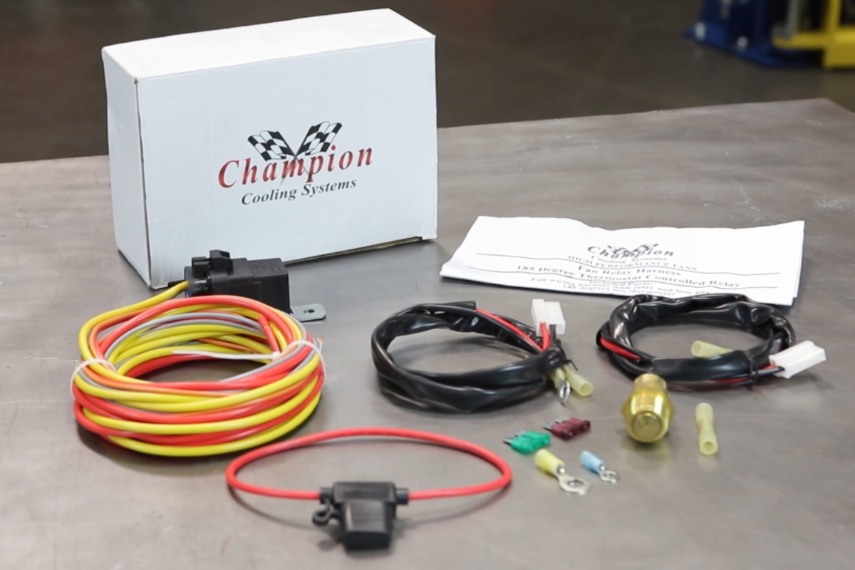
Connecting a single cooling fan is a rather straightforward system, it relies on a separate temperature sender to switch the fan on, or you can utilize the cooling fan output if you’ve installed an aftermarket EFI conversion. A relay kit, our part number CCFKRL, will include everything you need to properly wire up your electric cooling fans, with the exception of additional wiring needed to complete all of the circuits.
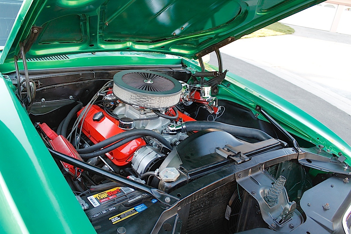
The first part of the installation is to install the electric fan to your radiator, and remove the mechanical fan. It’s unlikely you would have room for both, but you should never run a mechanical fan with an electrical fan on the same side of the radiator. If your mechanical fan had a fan spacer, it can be removed with the fan. Next, find a suitable location for the relay that is away from excessive heat, and someplace where it’s not exposed to the elements, such as water splashing up from the road.
The temperature sender, if used, is designed to provide a ground signal at about 185 degrees, and will shut back off when the temperature drops below 165 degrees. This wire (gray in our kit) supplies the ground signal to trigger the relay. The orange wire on the relay should see a 12 volt signal when the ignition switch is turned on. The other two wires on the relay are the meat and potatoes of the system, with the yellow wire connecting to the battery along with the supplied fuse mounted within 12 inches of the battery. For a remote battery, it can be connected to a power port in the engine compartment, but it should be fused.
The red wire from our relay connects directly to the cooling fan, and the black wire from the cooling fan connects to ground, both wires will utilize our supplied fan harness. If you purchase our relay kit, all required connectors are included to splice wires together. We highly recommend using a proper crimp connector, and following the directions in our instructions for a trouble free installation. Our video, below, will also help guide you through the installation.

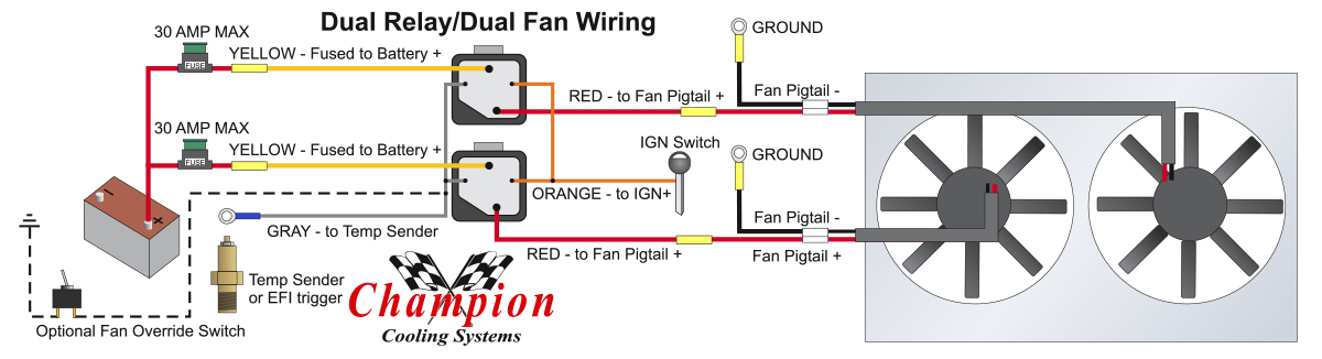
Wiring Dual Cooling Fans
With dual cooling fans, there are two methods for wiring up the relay kit. This is based on the draw from the fans, if the fans are larger and draw more than 15 amps each, it’s recommended to install a second relay kit as shown below. For smaller fans, both fans can be connected to a single relay as shown above, and the proper fuse should be installed to protect the circuit while at the same time providing enough current to flow without exceeding the fuse rating. If the fuse does blow, then it’s a sure indication that you have too much draw on the system and a second relay should be added.
For a second relay, both gray wires can be connected to the temperature sender, and both orange wires can be connected to your 12 volt ignition source. Each relay will control a single fan, and a 30 amp fuse is recommended for each relay connection to the battery. As you can see from the diagrams above and below, it’s really a simple circuit that not only provides the proper connections to control the cooling fans, but unlike the switch-under-the-dash method – you won’t ever have to worry about forgetting to turn the fans on.