
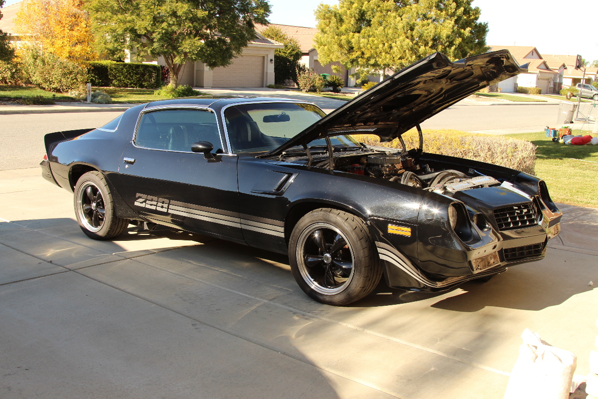
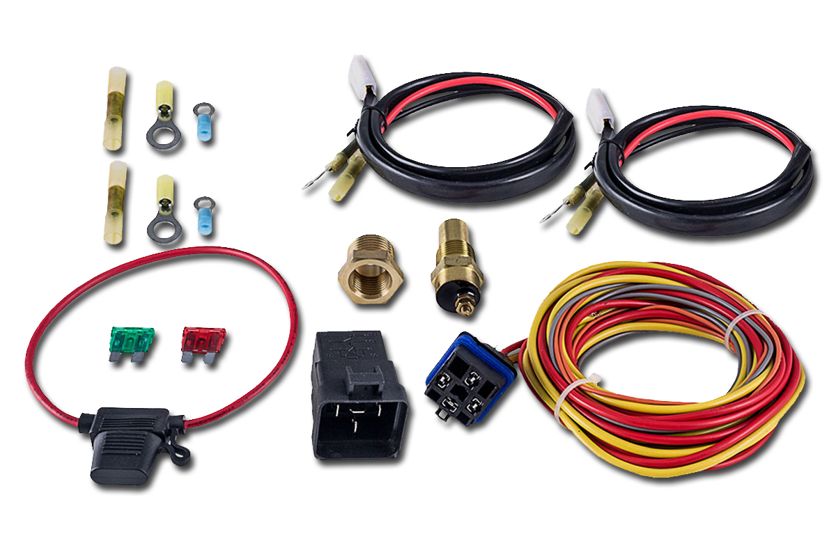
Our Project Cars all have one thing in common: they’re all cooled by Champion. While our Z/28 was already sporting an aluminum radiator wearing our cap, it wasn’t the setup Rick desired, so we decided to fix all of that and set him up with a complete cooling package which includes:
|
We basically installed everything Champion has to offer for this build upgrade, and we’ll give you something to follow along with if you’re doing your own installation. We believe in the Enthusiast, and we encourage others to do their own installs if you have the time and place. You’ll need some basic tools, a drain pan, a couple gallons of coolant, and a couple gallons of distilled water.
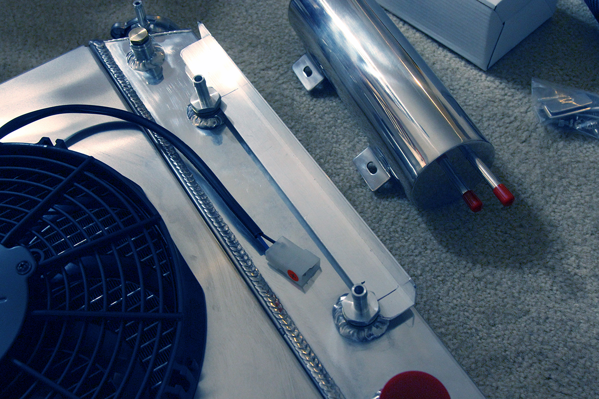
The first thing that we recommend is to pre-install all of your components. If your radiator is bracket mounted, mount the radiator to the core support and make sure you won’t have any interference with other components. It also allows you to make sure all of the holes line up. If you have a single electric fan to install, hold it up to the radiator to make sure you will have plenty of room, as the water pump pulley could interfere.
Determine the best spot for the overflow reservoir, and mount it someplace where you can access it and run the tubes. The reservoir works on atmospheric pressure, not gravity, and it doesn’t matter where it’s mounted relative to the radiator cap. It’s preferred to mount it near the radiator cap to keep the tubes shorter, but can be mounted anywhere as long as it’s vertical. This can be mounted to the core support, the apron, or a custom install like we decided to do.
Determine a spot for your fan relay(s), also. Make sure it’s somewhere that you can access with a dril/driver if you’re using self-tapping screws. They aren’t the easiest to install by hand, so a cordless driver, if you have one, will make the task much easier.
Also determine where the temperature switch will mount. It’s preferred to mount it in the intake manifold where it can read the temperature of the coolant inside the block (below the thermostat), but sometimes you may have to use another port. You cannot use the existing sender that controls your gauge – they are two different types of temp senders. The article reference will also provide alternatives if you need another port for the sender.
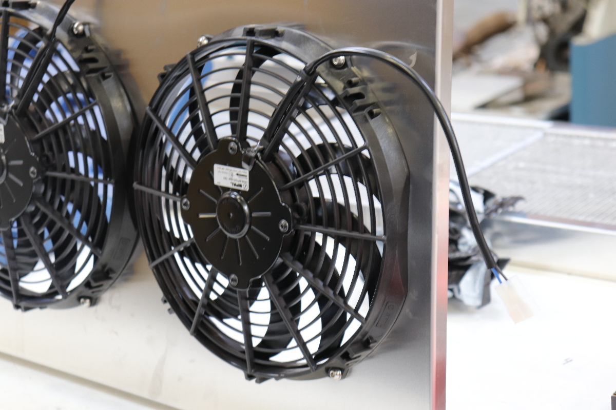
Mounting The Cooling Fans
The Camaro had a ‘flex’ fan prior to this installation. They might look cool, but they’re not very functional. The claim of a flex fan is that the blades ‘straighten out’ at higher rpms, which in turn creates less drag and frees up horsepower. The numbers are so minuscule that your butt-dyno probably won’t even detect the increase. Unless you’re a drag racer looking for every tenth of a second you can find, it’s not really that beneficial. Flex fans also begin to fatigue, and eventually won’t pull as much air as when first installed.
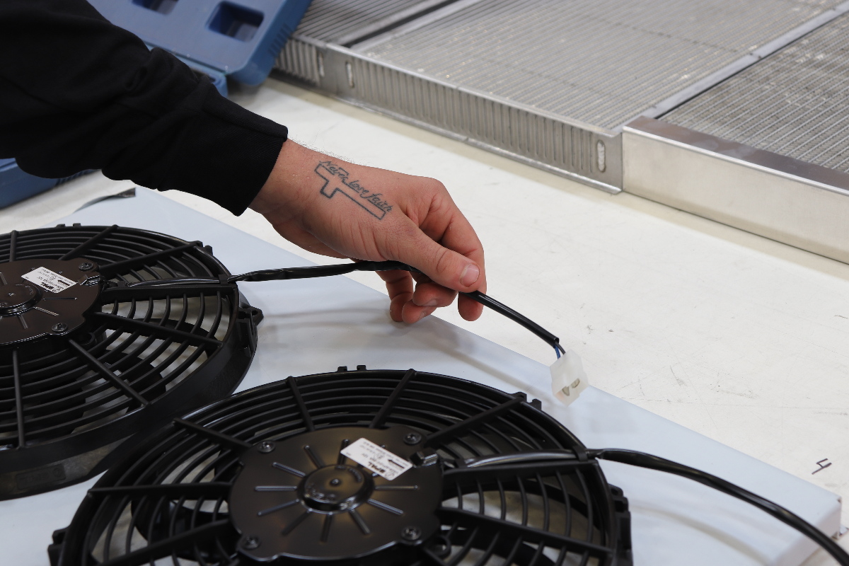
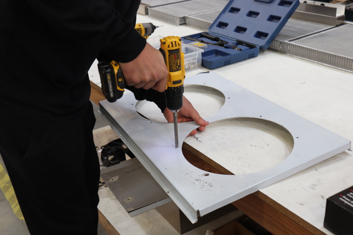
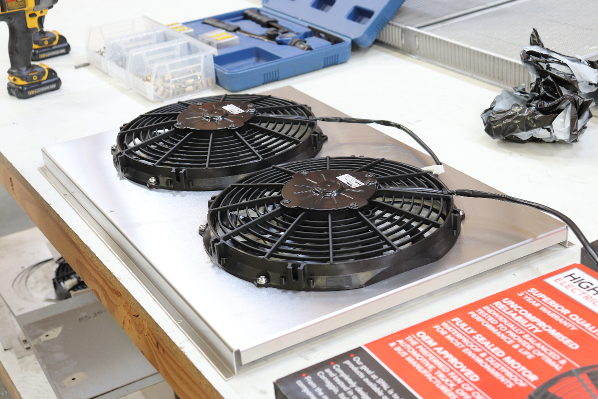
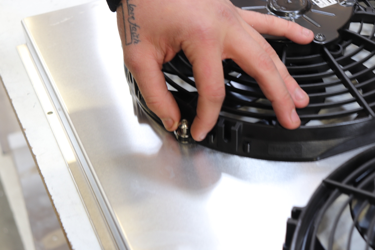
 Before removing the protective film, lay out your fans making sure to plan out where you’ll run the wires (top or bottom) so you won’t have to remove it later and flip it over. Mark the four holes, then drill accordingly. If you have a scrap piece of lumber around, put that under the shroud so that it keeps the aluminum from flexing.
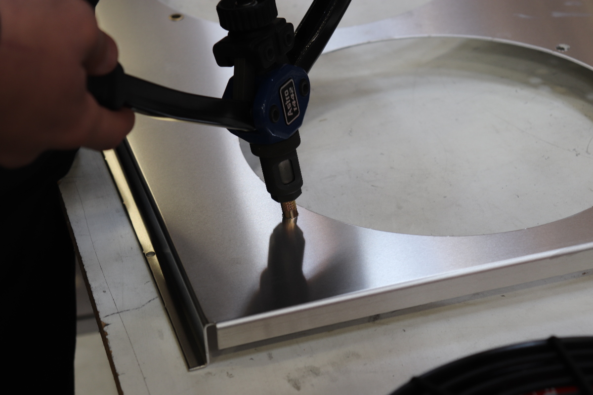
We opted to install nutserts, but you can just purchase (short) bolts and nuts to attach the fans. We don’t include hardware because there are so many different choices that we felt it was best to allow the enthusiast to purchase their own. Many times this ends up being stainless steel Allen-head bolts that can be purchases at any home improvement store. Hint: use antiseize on the threads, lock nuts work well, too.
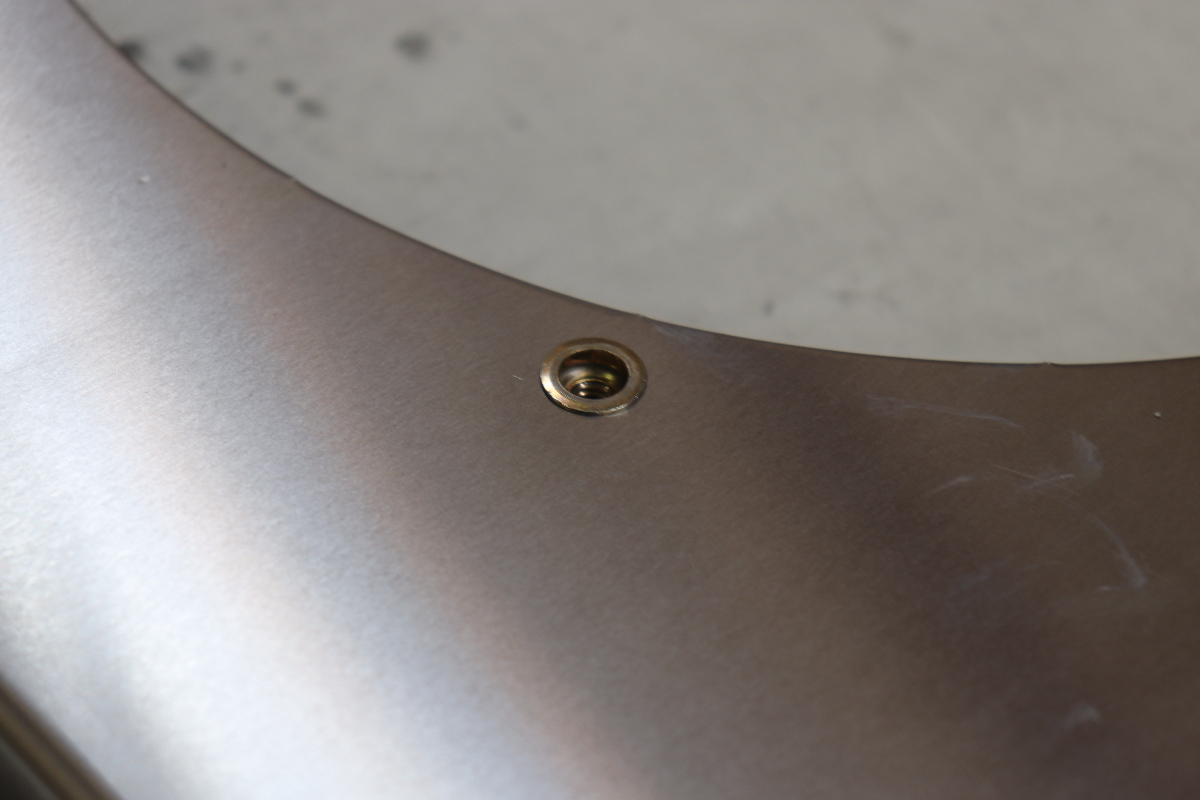
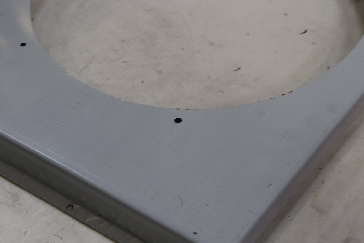
 Nutserts allow a clean installation, but there are two points to be made here. 1: Make sure you drill your holes on center. Using a center punch helps to keep the drill bit from walking. 2: When you install the nutsert, make sure you install it without tweaking the shroud. It’s easy to bend it when it’s sitting on a table like this, and that inhibits cross threading the bolt when you install it.
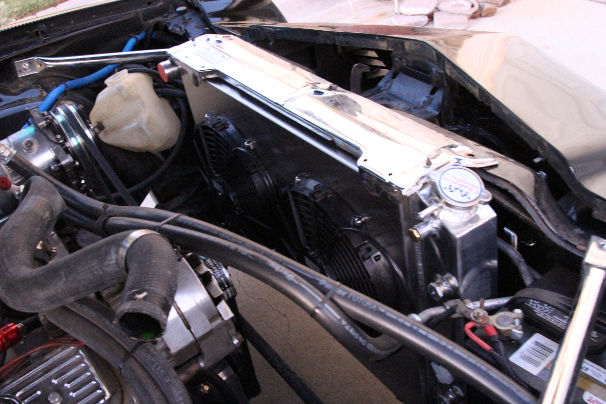
Now you can lay the radiator down on a flat surface and install the fan/shroud assembly using self-tapping screws. If using a drill/driver (recommended), be sure not to overtighten, and possibly stripping the holes. Trying to install the fan shroud with the fans mounted after the radiator is installed can be done, but reaching the lower mounting points might be difficult, and room/vision could be limited, so it’s best to mount the radiator with the fans/shroud mounted up.
Plan Ahead Before Removing Components
To install the new radiator, it means removal of other components as well, and not just the radiator. If this is your only vehicle, make sure you have everything before you start on your project, or you’re walking to the parts store (or bumming a ride). This means you should make sure you have the necessary hardware, inspect belts and hoses, and replace any that are worn. Now is the time to do it.
It’s also not a bad time to plan a little clean up if you so desire – without the radiator in place, there’s a bit more access room for replacing belts or other components. Our Camaro has been through much of this already with a fairly new Blueprint 355, so we skipped the additional parts and moved forward with the installation.

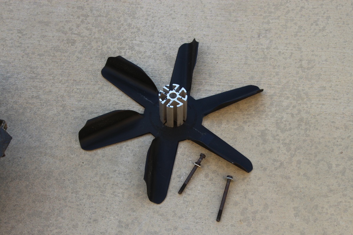
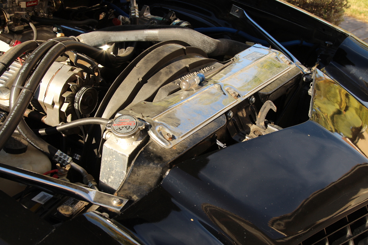
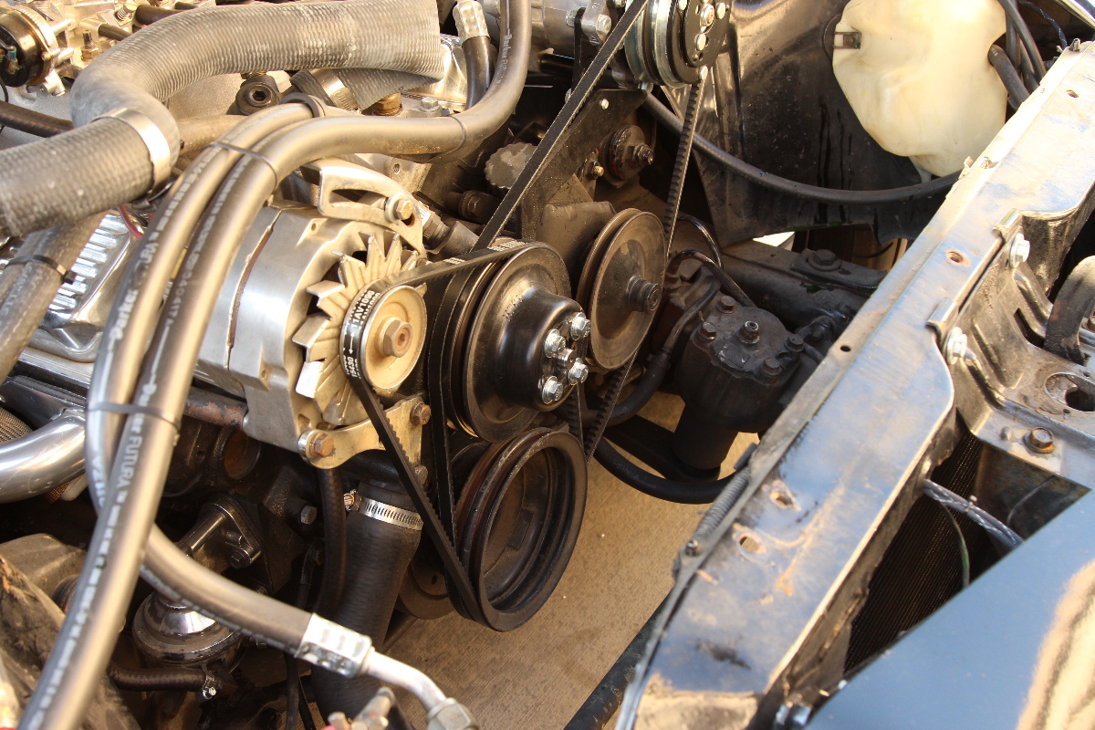 One part that often gets overlooked are those longer bolts used on the mechanical fan when a fan spacer is used. Once the fan is gone, shorter bolts are needed to bolt the pulley back to the water pump flange.
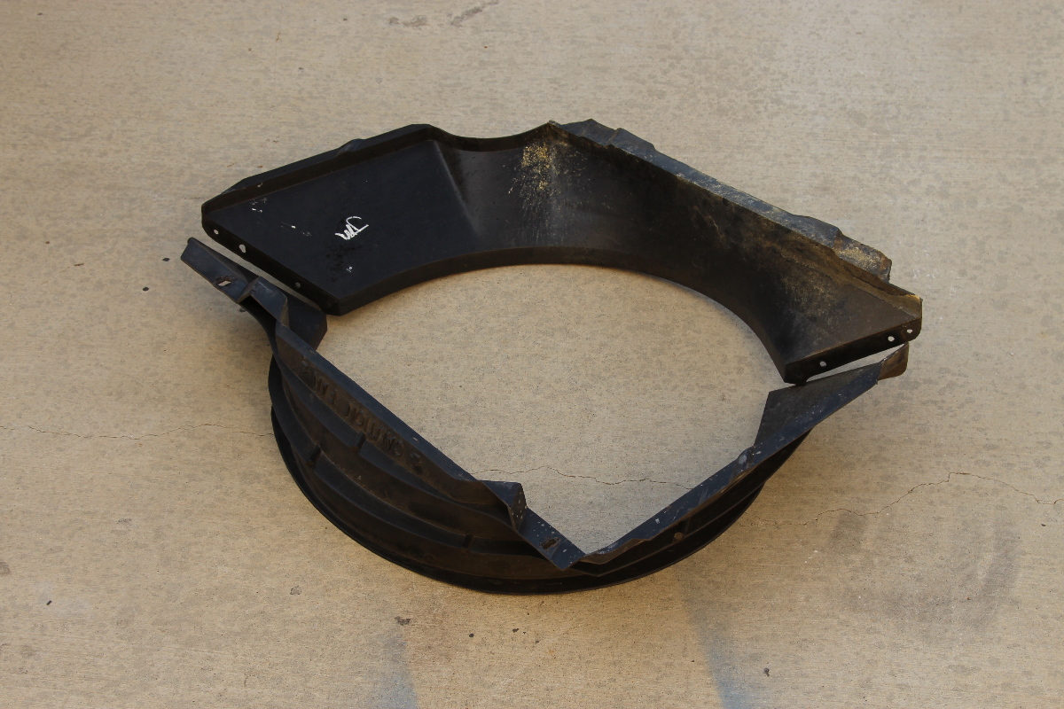
We no longer needed the plastic tank, or the factory fan shroud. And by adding electric fans means eliminating the mechanical fan. This is the part we were talking about when we said ‘plan ahead’. That mechanical fan had a fan spacer, and that means it had long fan/pulley bolts. Once the fan and spacer were removed, we were left with bolts that were far too long, and we needed to replace them with shorter bolts. Planning ahead like this saves you a quick trip to the parts store.
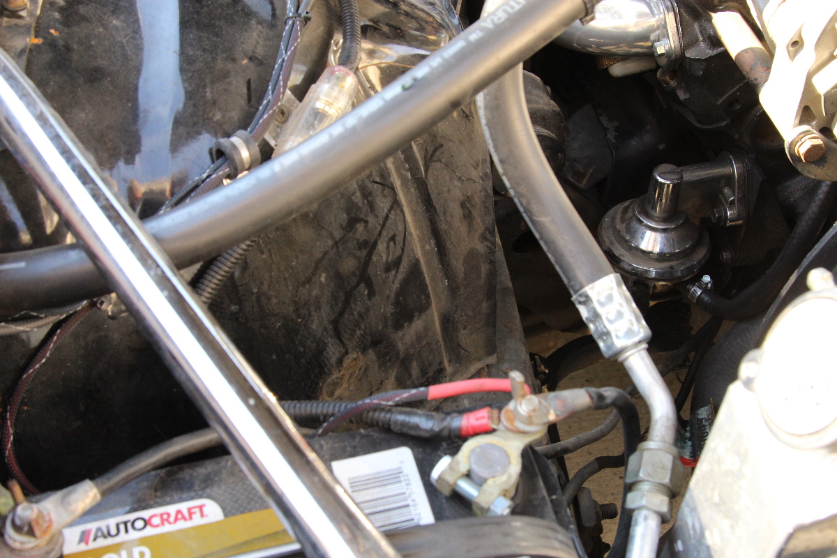
Since the battery is on the passenger’s side, we opted to mount our fan relays on the right apron to be closer to the battery. It’s not required to do this, however, keeping the power wires shorter means less resistance and less wire routing. This is also part of the planning process, and makes for an easier and cleaner installation.
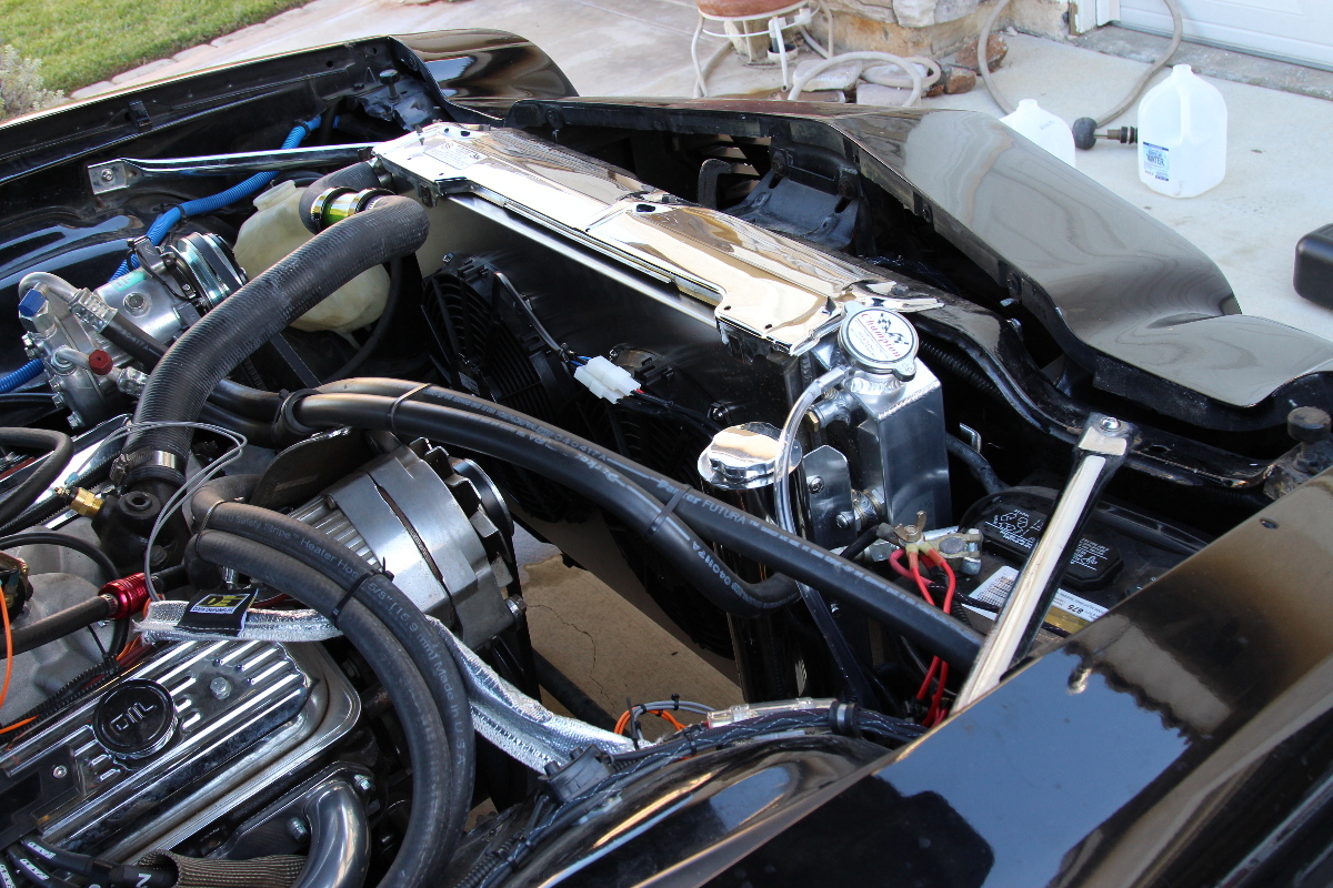
Finding Room For The Overflow Reservoir
When it comes to mounting the reservoir, there are a couple of options. One is to use the same mounting hardware that is provided, and the other is something a little more custom. There really wasn’t a lot of room for it in front of the core support, and the plastic OE reservoir was an odd shape because it was mounted to the apron, so that’s not a great spot for our reservoir.
Since the car has a manual transmission, we decided to utilize the automatic transmission cooler bosses for mounting the reservoir, and that took a little bit of ingenuity and creativity. This was another part of the installation that we planned out ahead of time, and while we want to encourage you to be creative and get custom, we also want to remind you to take your time when you forge into this territory.
 We always have extra scraps of aluminum stock in the garage from other projects, and we used what we had already, but a trip to a local home improvement store will provide you with all you need.
We acquired some inserts for the trans cooler and used some scrap aluminum leftover from other projects. Next, it was time to plan out the install, figure out where it was best to mount it and how to mount the bracket – and to do some cutting and drilling.
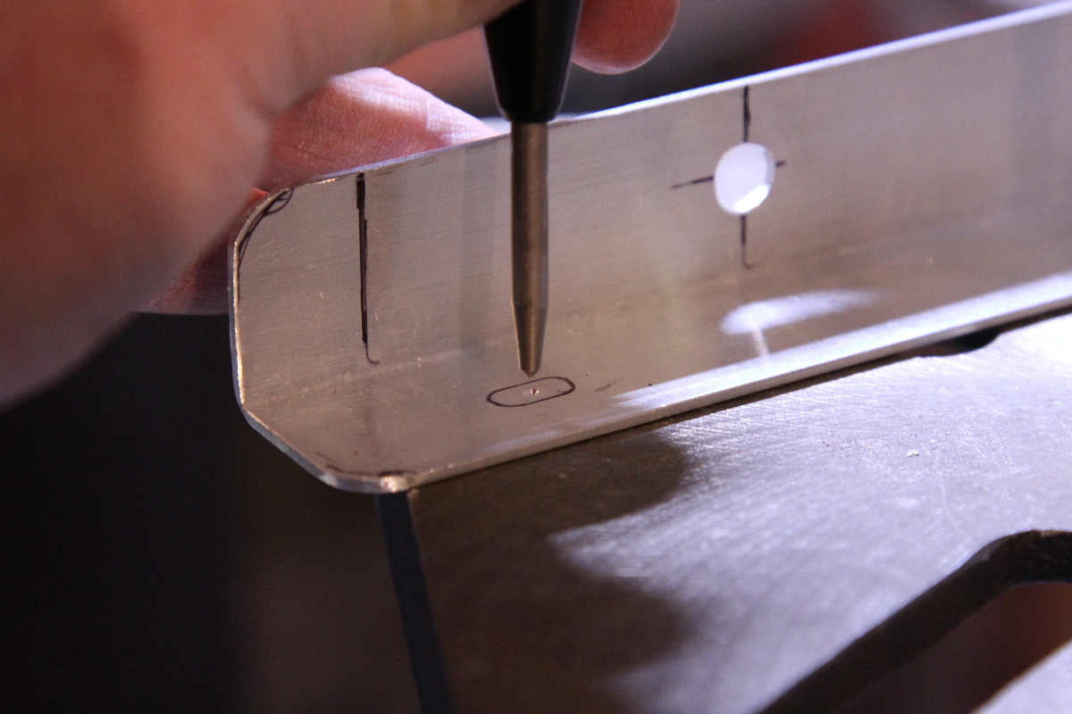
The first step was to cut and drill the mounting bracket, which was a leftover piece of angle aluminum about an inch wide. Here’s where you want to measure twice and cut once, and of course wear eye protection when using power tools. A good center punch is also a necessary tool when you want to drill precise holes, like with mounting the fans.

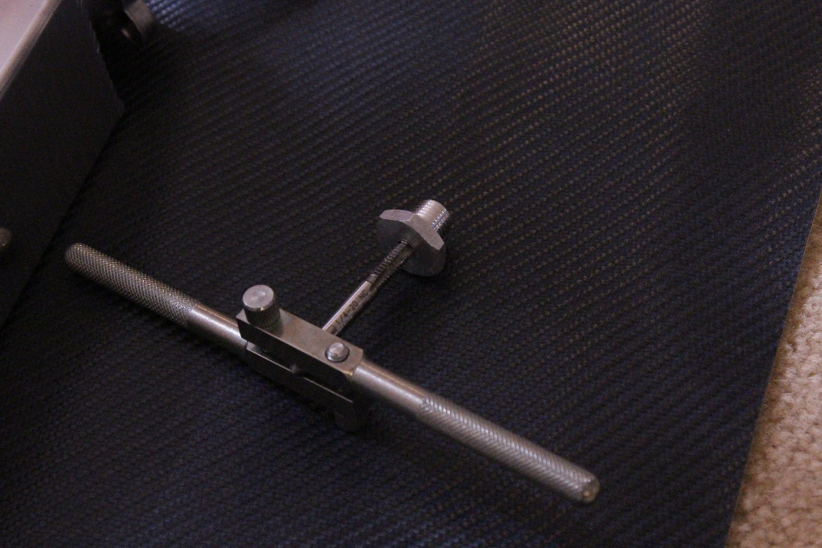 The aluminum adapters were perfect for this, but brass will do as well. Just make sure you have the proper screws/bolts and a tap.
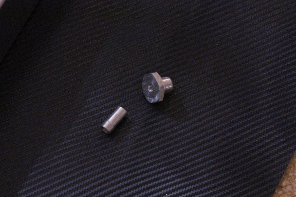
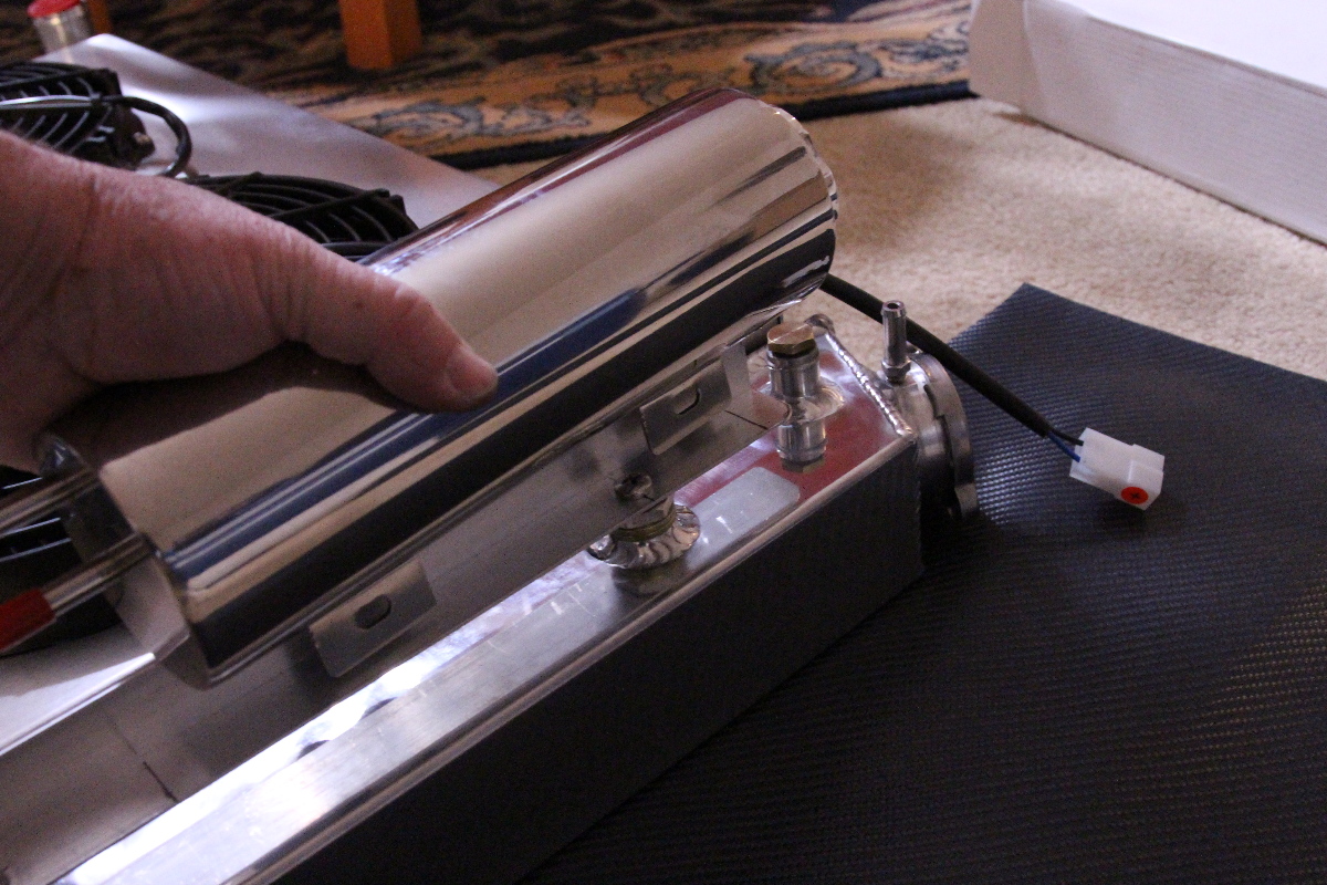
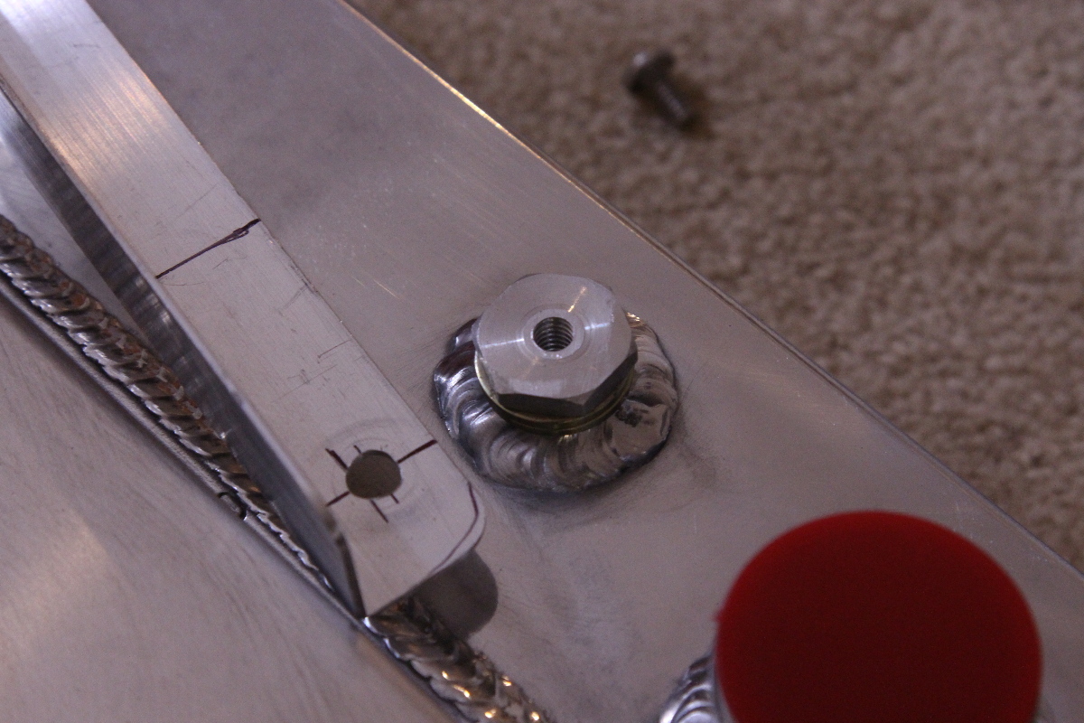
Mounting the bracket to the trans cooler meant more creativity, so we started with aluminum fittings that are typically reserved for the fluid lines, and we cut the barb fitting off of it, since that’s not being used. We tapped the center of it with a tap that was the same size as our mounting bolt and put the two pieces together.
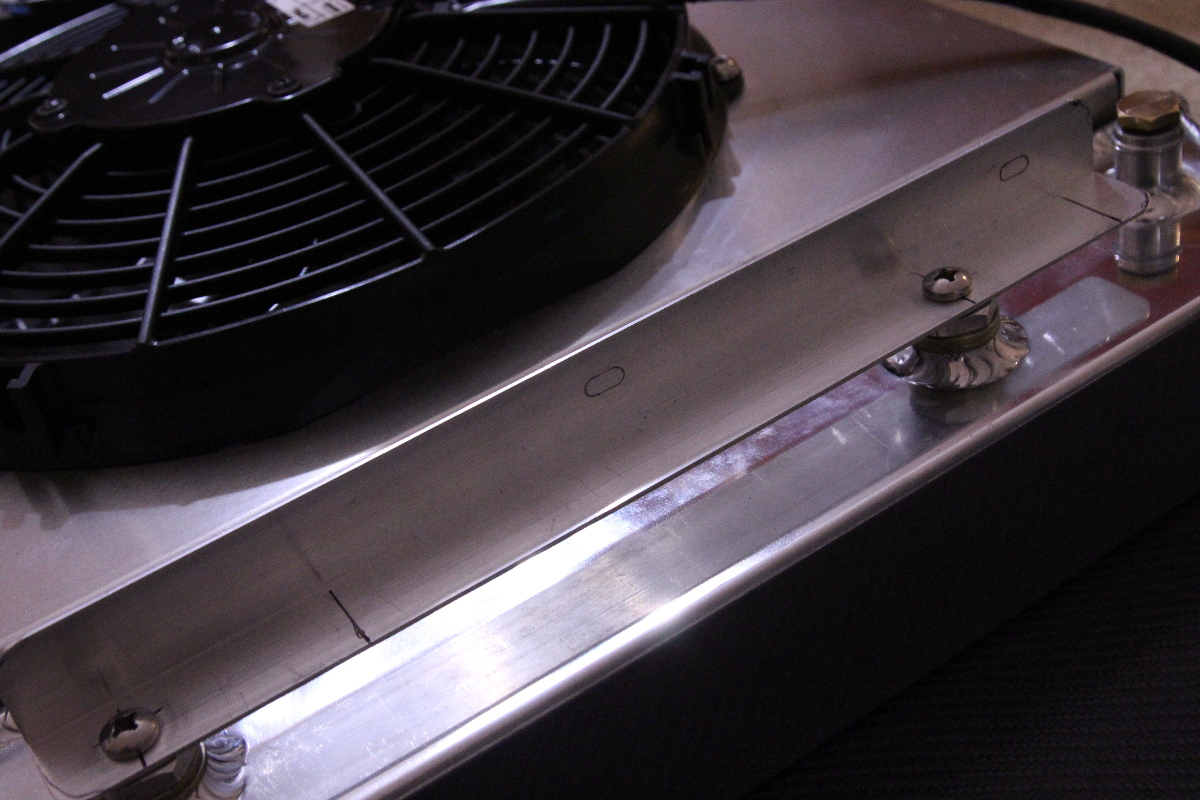
This allowed us to mount the bracket and then we determined the spot we wanted to mount the reservoir, and went through the same process of measuring and drilling the mounting holes. It’s important to remember here that you want to have first mounted the radiator and fans into the vehicle, and then made sure that the reservoir wouldn’t come in contact with any other components, especially moving components like the engine pulleys/belts.
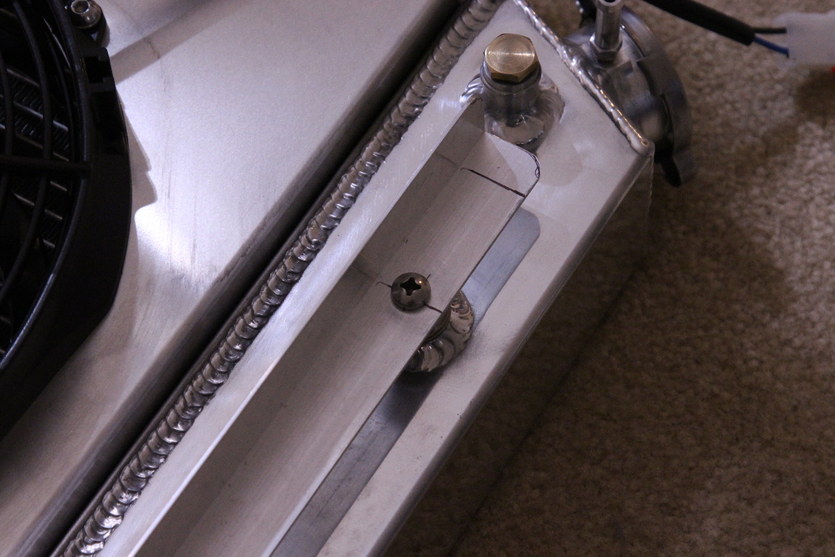
After some careful measuring and drilling, we did one test install to make sure everything would line up, then installed the radiator assembly into the car for the final time, and then after cleaning up our marks we mounted the reservoir and bracket.
Caution should be used when mounting the bracket and reservoir this way because the trans fittings are aluminum, so be sure not to overtighten them. We used blue Loctite on the threads to help secure the hardware. Mounting the reservoir in this manner isn’t something we haven’t seen before, and if you’re confident with hand tools, measuring and drilling then it should be a piece of cake for you.
 We used blue Loctite on the threads to keep them from coming loose from vibration. No need to overtighten these, just get them snug – aluminum is much easier to strip if you go at it too much.
Finishing Up The Electrical
For some, wiring is not their favorite part of the installation. But if you take your time, plan out your install, and cut and terminate the wires after they’ve been routed, you’ll end up with a clean electrical install. The relay kits we offer include the necessary terminals, and also includes plenty of electrical wiring for just about any installation.
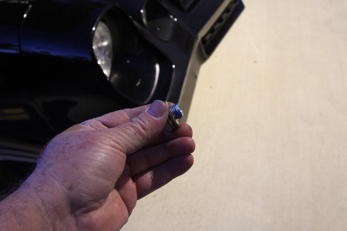
The first thing we wanted to do was to install the temperature sender, which is very specific to this type of install. The sender is basically an ‘on-off switch’ – it provides contact at 180º and disconnects at about 165º. For this reason, it cannot be used for a temperature gauge, nor can the temperature sender for your gauge be used for the fan relays.
Your gauge needle moves from cold to hot based on the resistance in the sender: a cold sender offers maximum resistance, while a hot sender offers the least resistance. If the temperature reaches the maximum (roughly 250º) then it is similar to grounding out the wire.
The best place for a sender is in the intake where it can read the coolant temperature before the thermostat opens. If you don’t have an extra spot for a temperature sender, we’ve provided some ideas and solutions in our article on temperature senders. If the sender is placed above the thermostat, like with our application, it will still work properly as long as your thermostat has a maximum reading of 180º. Any higher and it might not switch the fans on until the thermostat opens.
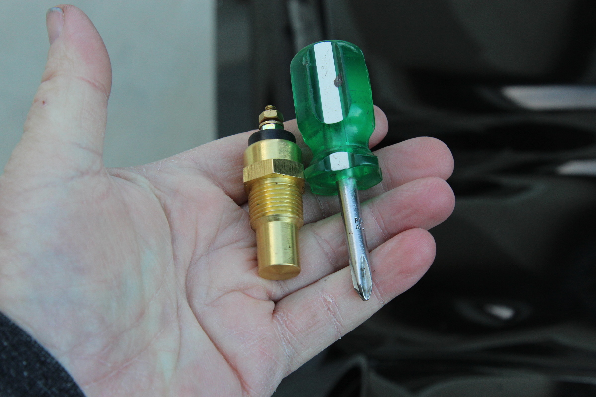
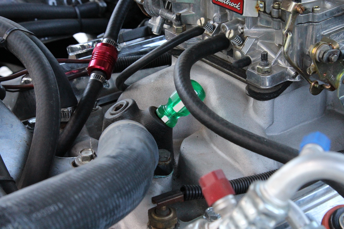
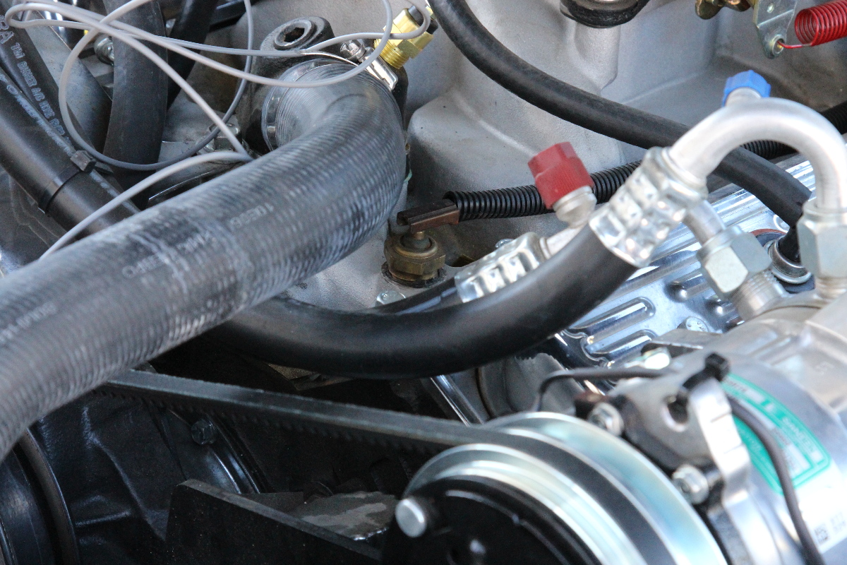
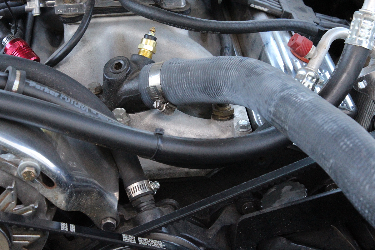 Mounting the sender to the top of the thermostat was our only option. We used a short screwdriver to make sure we had enough depth to mount the sender.
Since we were mounting it into the thermostat housing, we used a short screwdriver to check the depth of the port, to make sure that the sender probe wouldn’t come in contact with anything inside – like the thermostat itself.
Once we knew we had the space, we twisted it in by hand and then gave it a couple of turns with a socket wrench. It’s important to not use any type of thread sealer on the sender because it could interfere with the connection to ground. It has a tapered thread and will get tighter, so once it’s installed and functioning it should not allow coolant to escape. If you see a couple of drops, just give the sender another quarter turn until it seals up.

Cooling Fan Relays
We picked a spot on the apron where we could mount the relays, making sure that any sheet metal screws used to mount them won’t interfere with the tire in the wheelhouse. We marked it and then center-punched the metal so that when we drilled the pilot holes the bit wouldn’t walk and scratch up the finish.
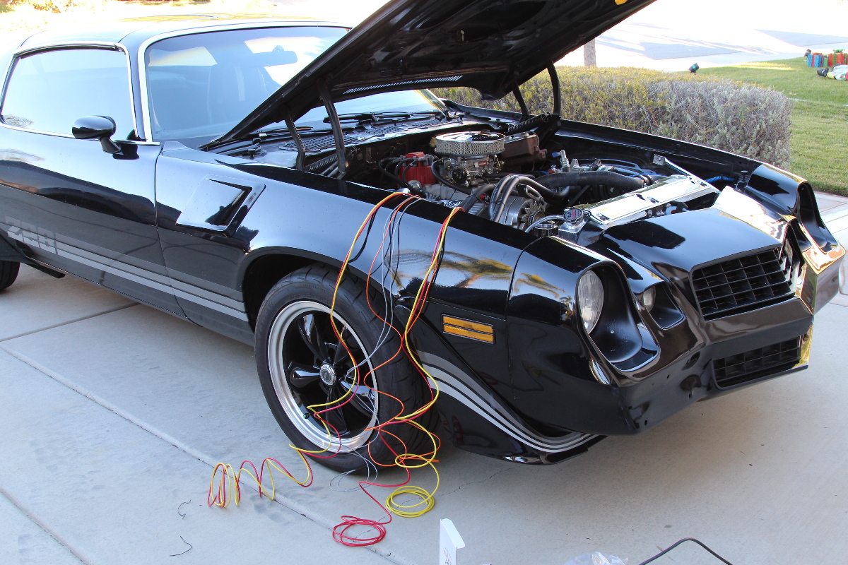
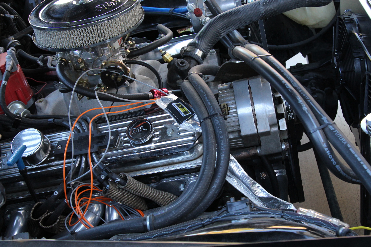
After mounting the two relays, we draped the lengthy wires over the fenders to separate them and decide where to route them. You will have four connections to make with the relay:
- Gray wire – connects to the temperature sender (ground)
- Orange wire – connects to a switched 12-volt source (ignition)
- Red wire – connects to the red fan wire
- Yellow wire – connects to the battery (using supplied inline fuse)

 The wires are long enough in case you need to route them across the vehicle to the opposite side or into the interior. NOTE: the orange ignition wire should not be connected to the battery, otherwise the fans will continue to run until the internal temperature reaches 165º or lower.
The gray (trigger) wire can be spliced together, or run both to the sender and attach using the supplied ring terminals. We kept both of ours long and separate because we planned on installing a Dakota Digital dual fan controller after this installation. The orange wires can also be spliced together, and connected to an ignition source; we used the same source for the electric choke on the carburetor.
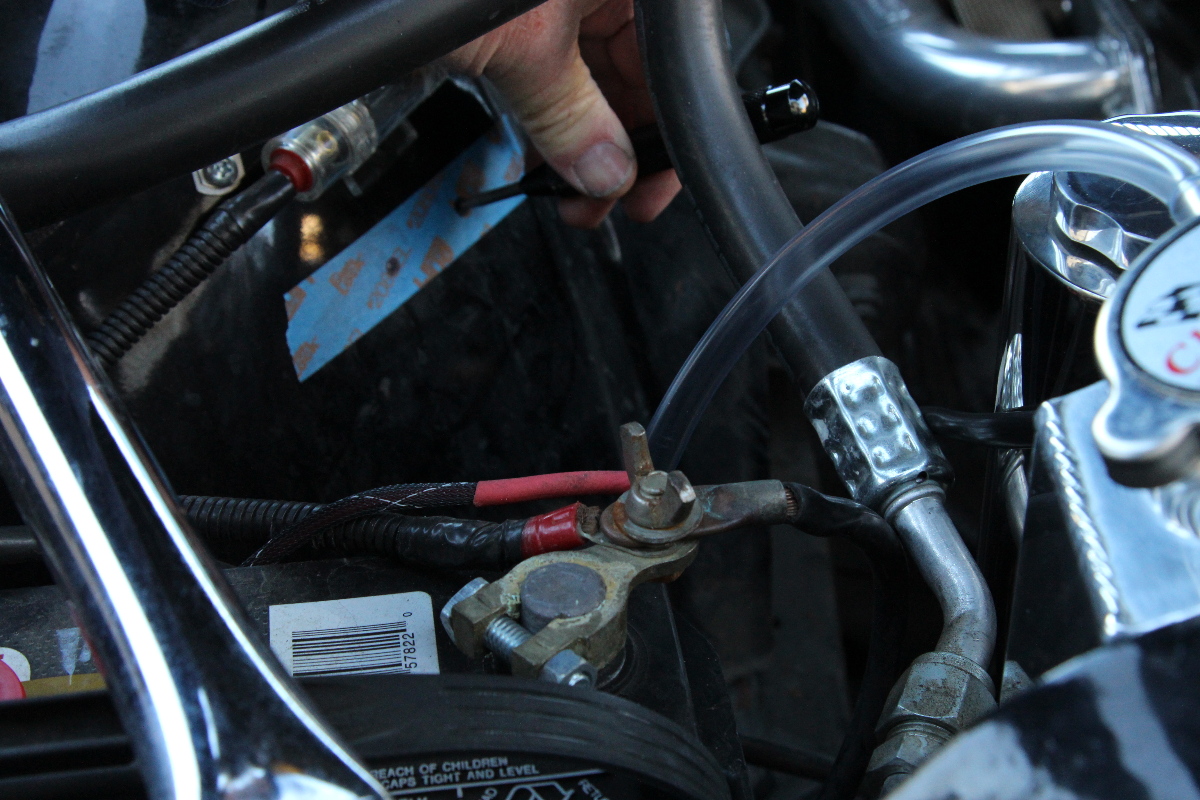
We ran the yellow wires directly to the battery positive post using the inline fuses supplied, then ran the red wires to the fans’ red wires, then connected the fans’ black wires to our battery ground (any solid ground source will work).
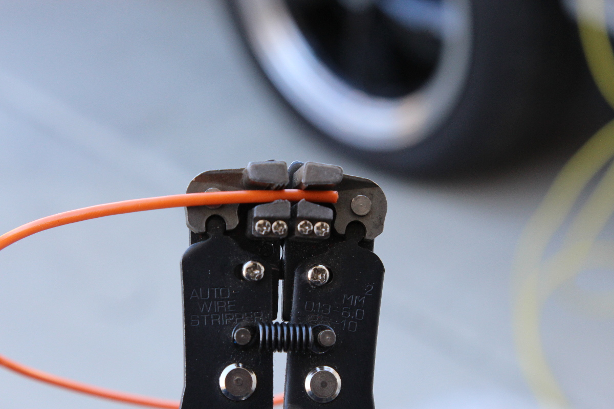
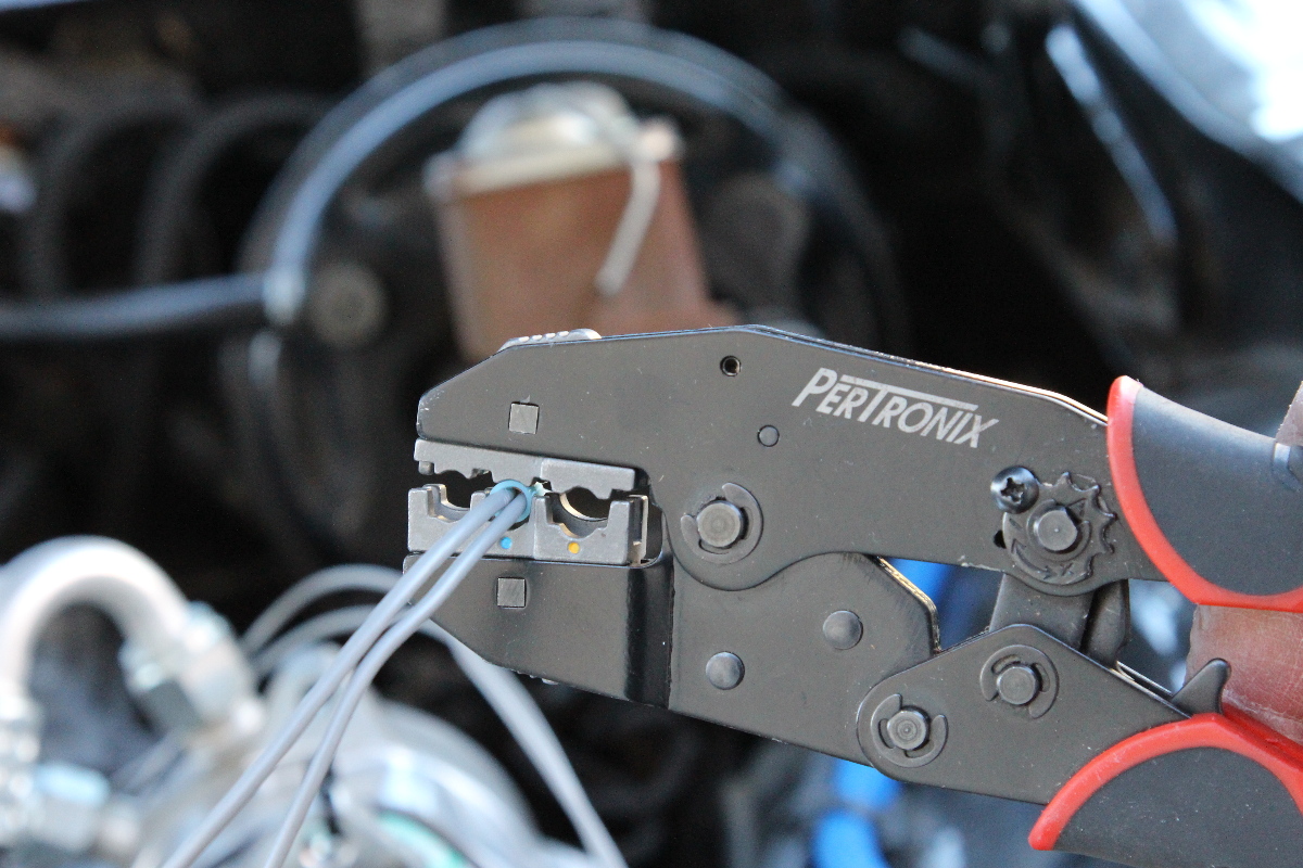

 TOP: Using the proper tools will make the job easier, and look professional. If you do a lot of wiring projects, it’s worth it to spend the extra money to get better results.
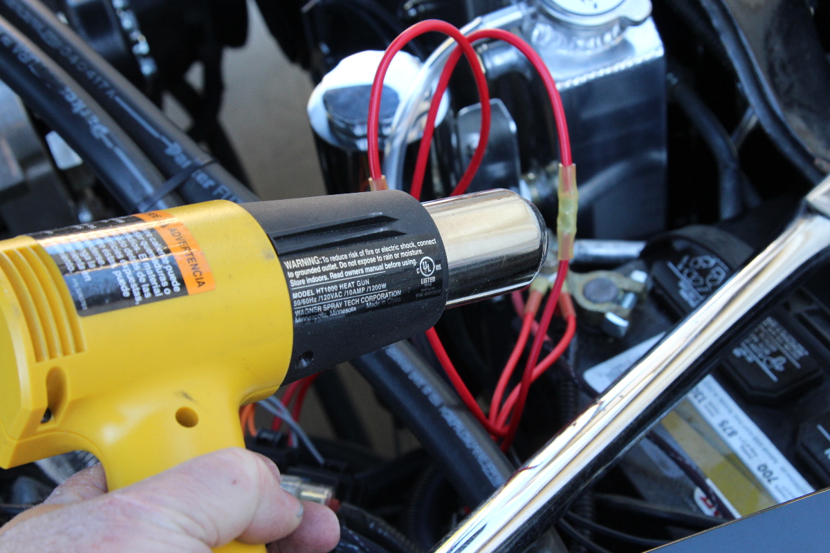
BOTTOM: each of our electrical terminals utilizes a heat shrink tube to seal the wires. While a lighter will work, a heat gun works best because it allows you more control over the direction of the heat, and keeping it consistent.
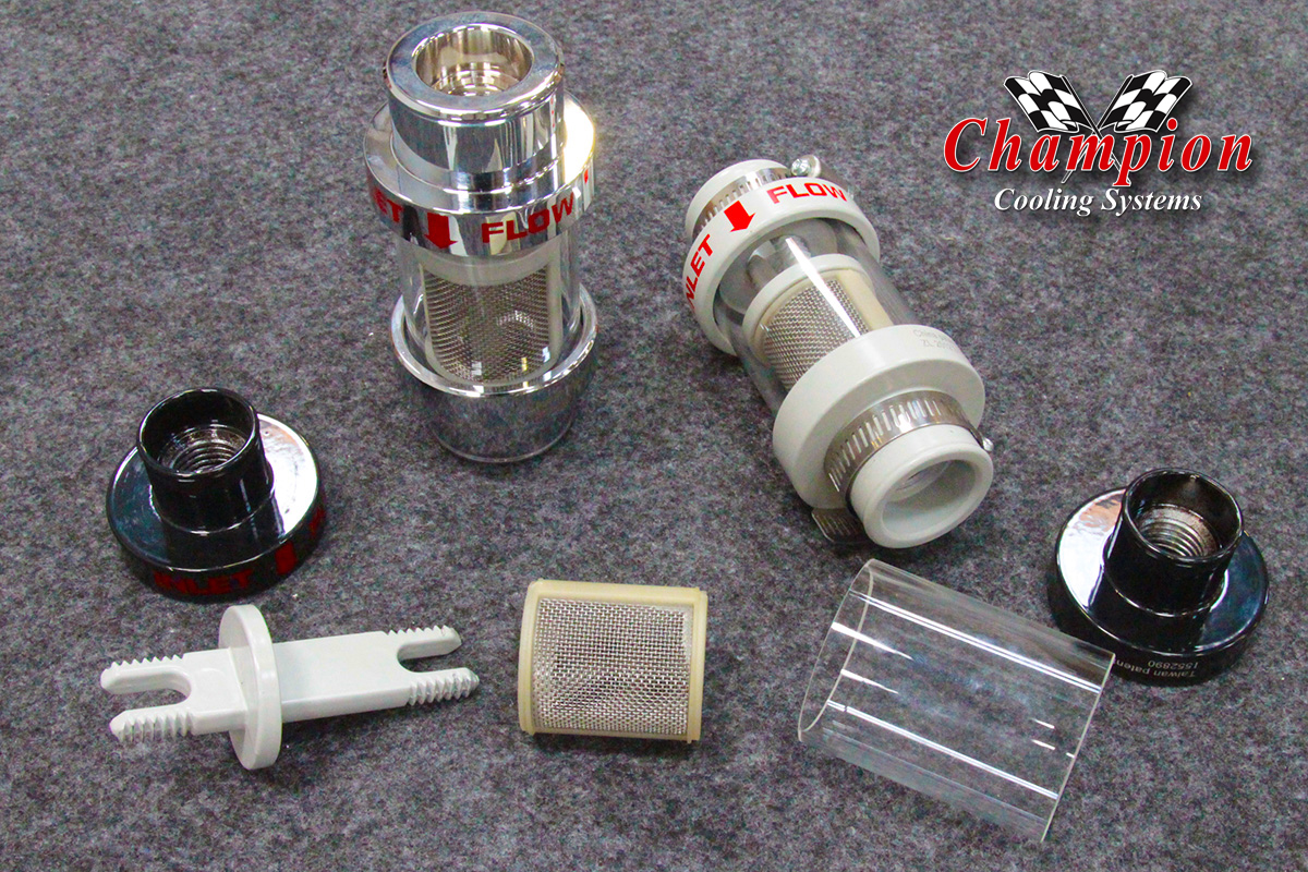
Installing The Inline Filter
The inline filter always mounts in the upper hose, and is available in three sizes, and three finishes. There is an instruction sheet included, but we’ll give you some pointers here to help you install yours. It should be mounted in a straight hose section of about 5-6 inches, and close to either the radiator inlet, or the thermostat housing.
Mounting the filter in the middle of a long hose might cause the hose to sag and the filter or hose might come in contact with moving parts, so find a suitable location before you start cutting.
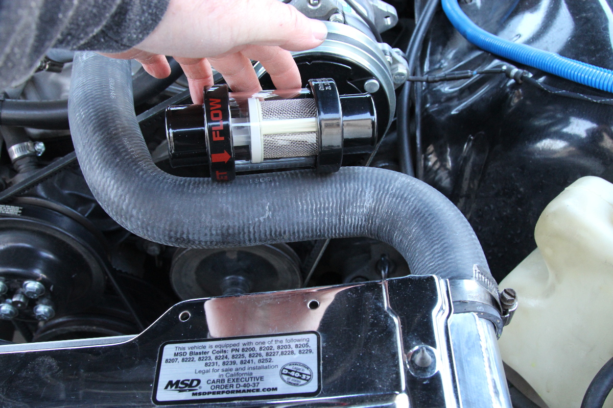
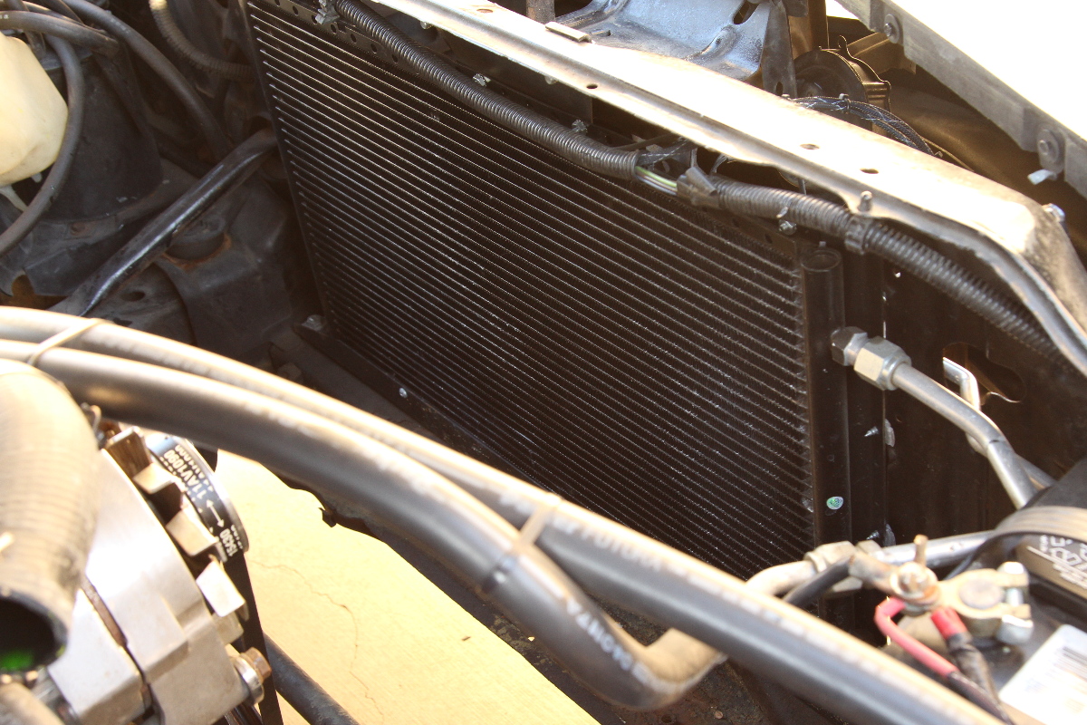
For our application there was a perfect spot where the hose runs alongside the radiator, clear from any of the moving parts. With a straight hose, it’s very important to make the proper measurements before you cut the hose. With a hose like ours, we were able to fudge a little because the hose had some wiggle room.
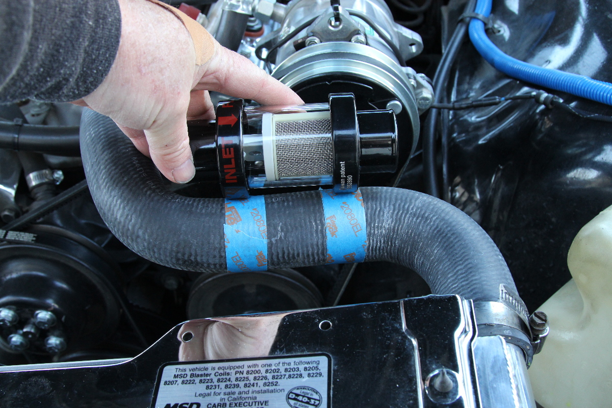
Since we haven’t added our coolant yet, there was no need to drain anything, but even with a full radiator you will only need to drain it below the inlet. We removed the hose and marked it with tape and then used a marking pen to place our cut lines. A sharp utility knife will work, or a very fine-tooth hacksaw can work as well. The important point here is to make slow, straight cuts.
 We had some play in where we made our cuts, so we cut a little less out of the hose than listed in the instructions.
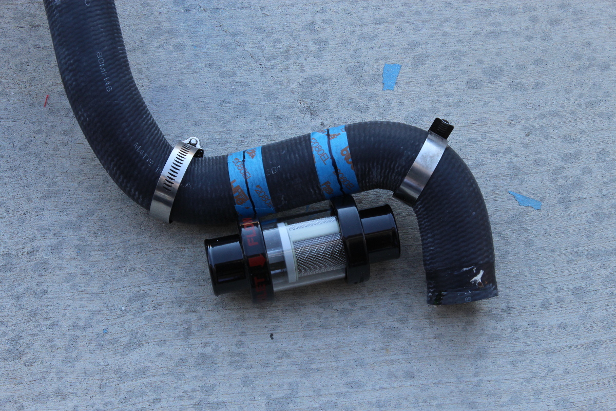
Another important thing to consider is that a portion of the filter will reside inside the hose, and you will need to make sure that you can securely clamp the hose onto the filter. This means that any sharp curved section of the hose (like the elbows in ours) need to be away from where the filter mounts. For that reason, we cut a smaller section of hose, and spaced the hose further apart.
Likewise, when you have a straight hose, keep in mind that the upper radiator inlet is there, and make sure you leave room for the filter to be clamped onto the hose, without the filter contacting the radiator inlet.
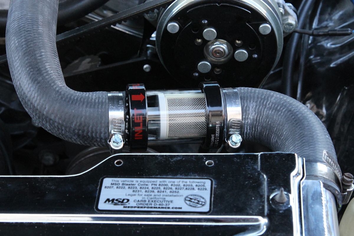 Once installed and clamped in place, you can see how we had a little room to work with.
Adding Coolant/Distilled Water
We often get asked what the best mixture is, and which type of coolant to use. We’ll typically recommend a 50/50 mixture of distilled water and Prestone concentrated (green) coolant. There is no need for the fancy coolants, or the type commonly used in newer vehicles. That type of coolant is recommended for a closed cooling system (not vented to the atmosphere) whereas the conventional coolants work well with a sealed/vented system, such as on this Camaro.
Distilled water doesn’t contain the chemicals in tap water, and while some prefer the pre-mixed coolants, we feel you’re paying a lot for that half-gallon of water in the pre-mixed jugs. Distilled water is about a dollar, and if you purchase two gallons of Prestone concentrated and two gallons of distilled water, we have a trick for putting it in your radiator.

Open your radiator cap and pour one gallon of the distilled water in first. If you forgot to close the drain petcock or tighten your lower radiator hose, you’ll be glad you only wasted a little water. Then pour in one gallon of coolant. Now you have two empty jugs, so fill the empty coolant jug with half of the remaining jugs and you’ll have two 50/50 mix gallons left over.
Pour the first gallon of 50/50 in the radiator as needed, and save the second gallon of 50/50 mix for a spare to fill up your radiator anytime you need it. Some systems will only take a couple gallons (initially) while others might take up to three gallons. Once you’ve filled the radiator, install the cap and start the engine and let it get up to temperature. Here, you can verify fan functionality as well. After it cools down and the pressure subsides, check the level and add as necessary.
When the engine is warm, you can check the level of the overflow and keep it about half-full. When it’s cold, don’t add coolant at all. As the temperature rises, the coolant will expand and begin to seep out of the filler and into the reservoir as the pressure rises.
When the temperature decreases, the reduction in pressure will create a vacuum and pull some of the expelled coolant back into the radiator. After a couple of cycles, you should check the levels and only add as needed, and let the cooling system maintain its own level. If you continue to add more coolant, you might just end up wasting it as it starts to fill the reservoir. If you see a puddle after you return to your car – you probably had too much in the reservoir, so don’t panic until you verify where the coolant came from.