
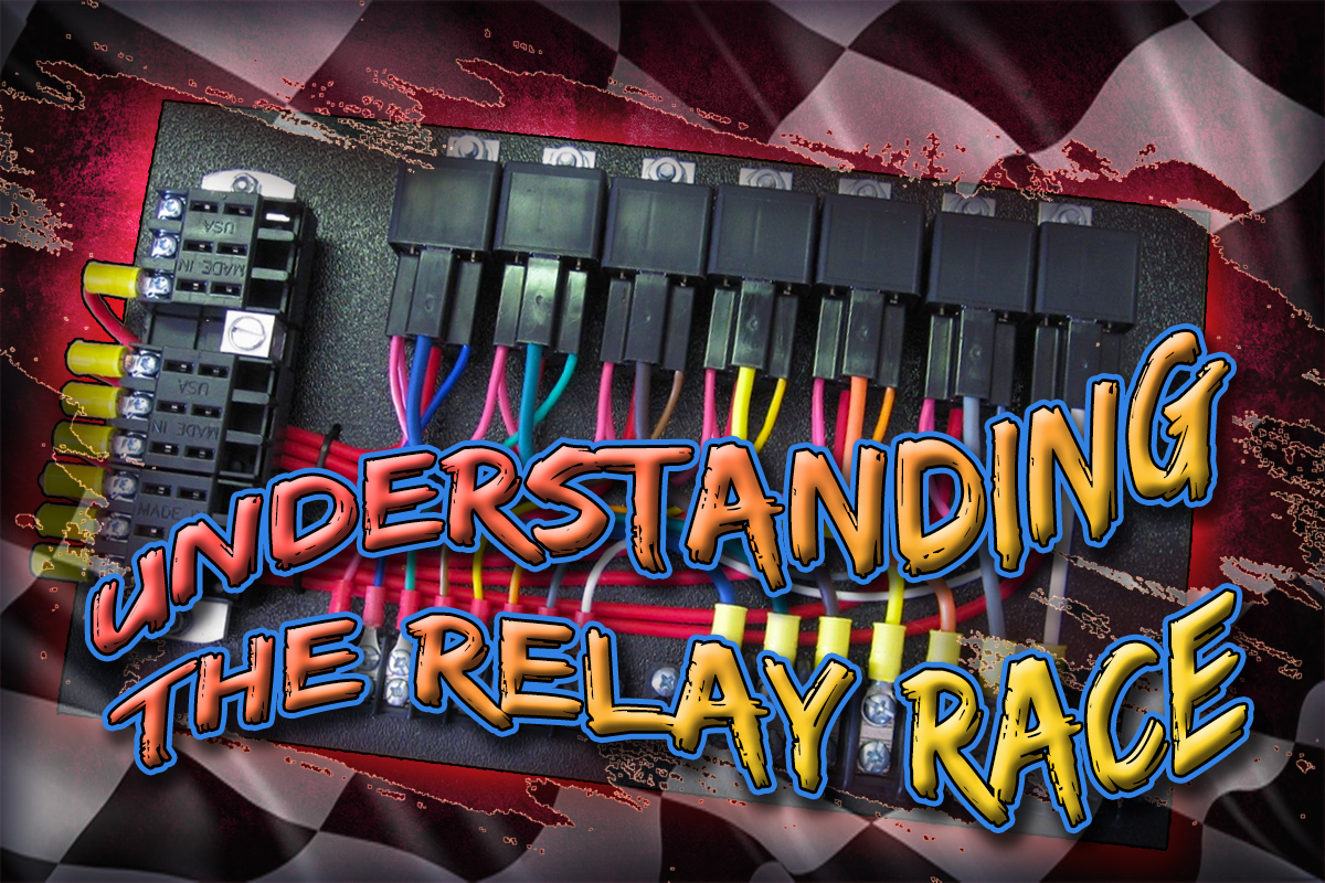
Most of us, at one time or another when we were young, probably tried to control fog lamps, driving lamps, or even an electric cooling fan with just a switch. That was likely the moment we learned that we needed to upgrade our wiring to handle the current load without risk of melting wires or causing a fire. More current means more heat, and to keep the heat down you need to decrease the resistance; you can do that with thicker wiring, and adding a relay.
For those who are familiar with Ohm’s Law, there are some simple formulas to help calculate all you need to know about current, resistance, power, and voltage. But you don’t really need to learn all of those formulas, because most components already supply the amperage rating, like they do with SPAL electric cooling fans. When it comes to lighting, you’re given another part of the formula, and manufacturers typically indicate the light output in wattage.

When it comes to the wiring in our vehicles, it can be a bit misleading if you want to add components. There’s a catch that many are unaware of with factory wiring harnesses; when the factory builds a vehicle, they’re looking to cut costs, of course, so they’ll determine what gauge wire is the thinnest they can get away with and still carry the load.
When you use thousands of miles of wiring in a vehicle, you save money by using the smallest gauge wire you can get away with. So they calculate the resistance in the wire with the given current and voltage rating. If the wire is too small, it will get hot, so they use a larger wire to handle the current load. If you have tapped into an existing fusebox to add an accessory, you’re not the first, or the last.
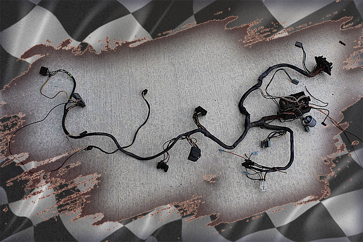
If you’re adding an accessory to an existing circuit, you might find yourself quickly overloading that circuit, because the factory didn’t count on you adding fog lights, a power amplifier, or a cooling fan. That also means that the fuse in that circuit is likely not meant to add another 15+ amps, and that’s when you’ll need to add another fused circuit and get your power from the battery.
Adding a switch to control a relay to power that component typically isn’t an issue, since most automotive relays draw very little current to begin with. While the component you’re adding might be 15-30 amps, the relay requires just milliamps (mA), most likely in the 150-180mA range. That’s why the wiring used to switch a relay is typically 16-18 gauge, while the meat and potatoes of the relay is often up to 10 gauge wiring.
The 4- and 5- Prong Relay
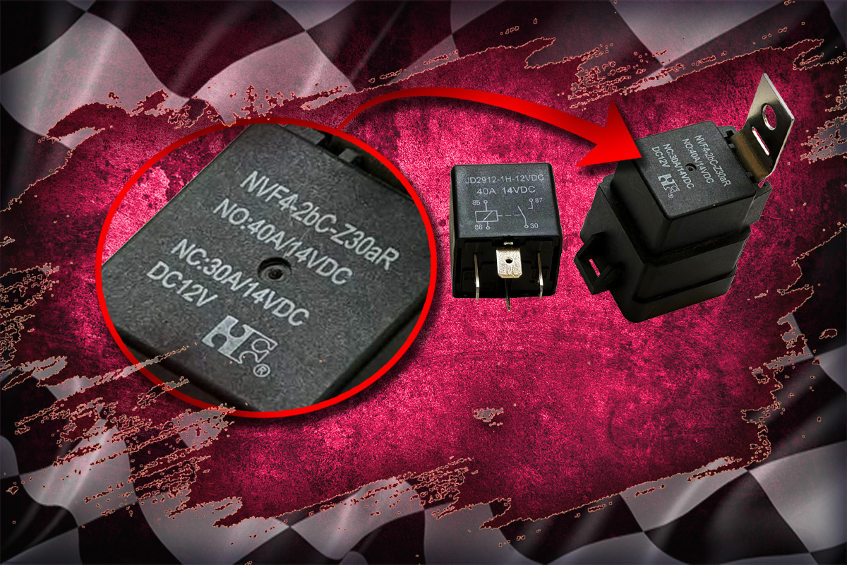
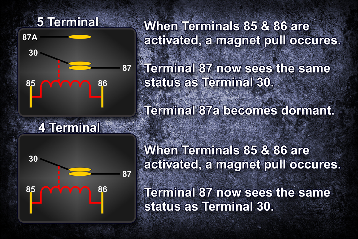
When looking at the specifics on relays, many provide a small wiring diagram, and likely include the voltage and amperage capabilities, or limits. The five prong relay often provides another piece of information: the Normally Open (NO) amperage and the Normally Closed (NC) amperage rating. While this may be confusing, it’s just specifications that are typically required by ISO – International Organization for Standardization (yeah, we know, it’s backwards).
The NC circuit refers to the connection between the 87a terminal and the 30 terminal. This is a closed circuit while the relay is at rest, or deactivated. When the relay is given power across the 85 and 86 terminals – the switching circuit – then the 87a terminal goes dormant, and the 87 terminal and the 30 terminal are closed, providing power from the battery to the accessory. This would be the NO circuit, and typically has a higher amperage rating than the NC circuit.
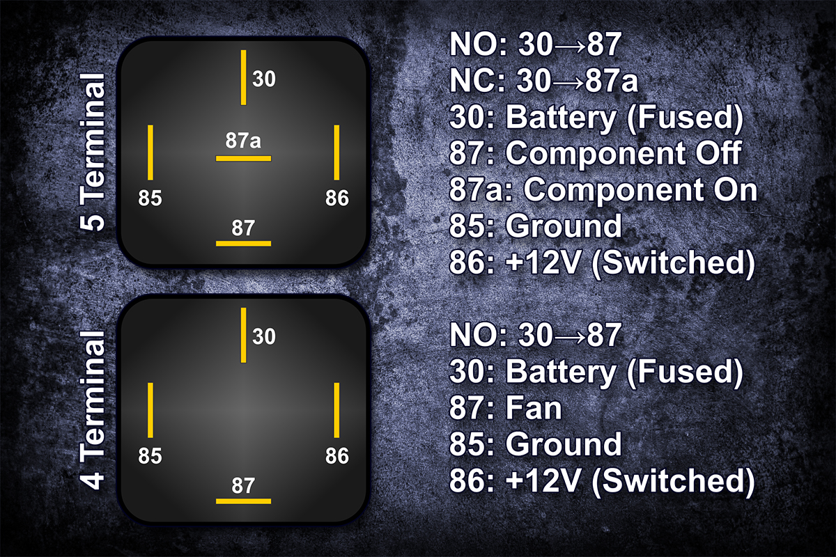
Though a four prong relay is typically all that is needed for an accessory, such as a fog lamp, driving lamp, or one of our SPAL electric cooling fans, however, the five prong relay can still be used. The 5th prong would come in handy when there is a need for a lighted switch that changes colors between on and off modes. For example, if the switch has a green LED when the component is off, but the LED is red when the component is activated, the 87a terminal can be used to supply power to the green LED circuit on the switch.
This additional wiring should only be done by someone with experience with automotive wiring. Champion doesn’t currently provide lighted switches for our fans, primarily because our cooling fans are activated via the thermal switch that is included with our single and dual relay kits. Though you can use a bypass switch to control the fans, the switch would be wired to ground, and therefore should never be connected to the 5th (87a) terminal.
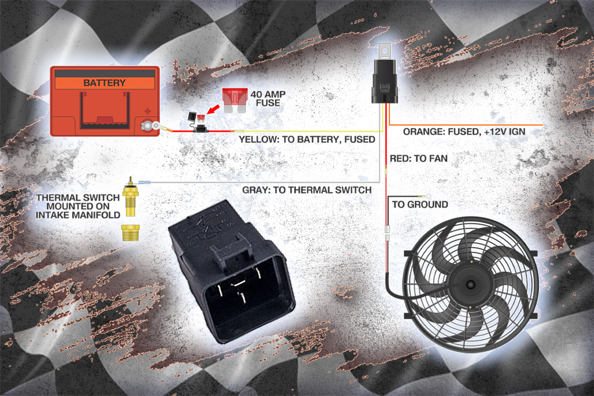
Champion Cooling Fan Relay Kits
In the illustrations below (left), you can see that the 85 (gray wire) and 86 (orange wire) terminals are connected via a coil that, when activated, makes the connection between the 30 (yellow wire) and 87 (red wire) terminals. At rest, when the relay is not activated (temps below 180º), the fan (red wire) is neutral, even when the ignition is on (orange wire).
In the illustration below (right) when the temperature reaches 180º it closes the thermal switch, which supplies the necessary ground signal to activate the relay. At that moment, the coil inside the relay becomes magnetized, and pulls the switch closed to connect the fan (red wire) to the battery (yellow wire – fused). When the relay is wired properly, you should have no issues with your fans turning on when coolant temperature reaches about 180º, and turning off when the temperature is reduced to about 165º.
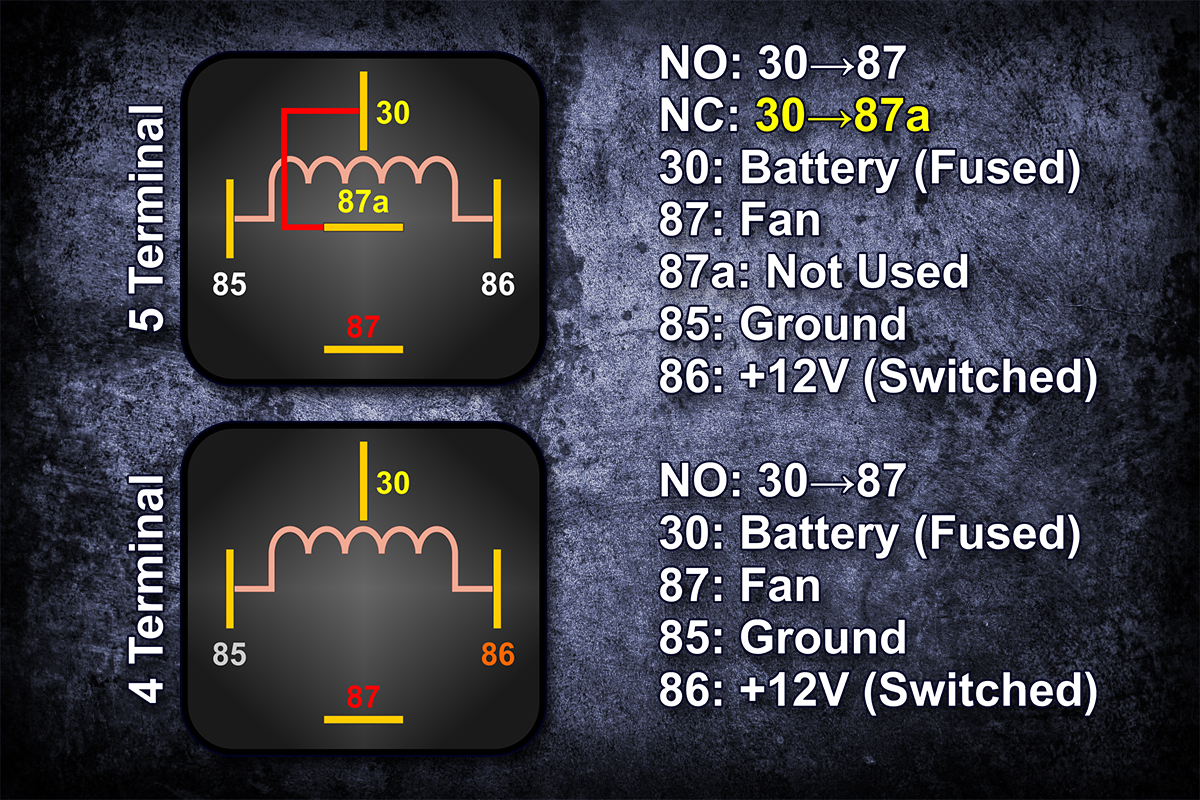
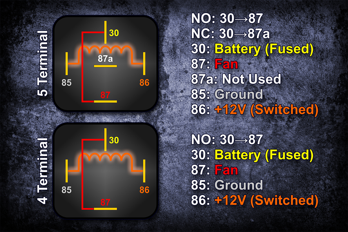
When wired properly according to the installation instructions, your fans should function properly. If the fan does not turn on by the time the temperature reaches above 185º, you should turn the engine off and check your wiring for proper connections.
In the illustrations below, you can see the inner workings of the relay, and how the connections are made. At rest, and up to about 180º when you’re driving, no connections are made to your cooling fan circuit. When wired per the included installation instructions, the orange wire (86) will see +12V with the ignition on, but the relay will need the gray wire (85) to be grounded in order to activate. This happens when the thermal switch closes at about 180º.
Once the thermal switch closes, the magnetic pull causes the plunger to close the connection between the yellow wire (30) and the red wire (87) to activate your cooling fan(s). Always remember to double check all of your wiring connections for a proper crimp and that they are terminated at the correct location.
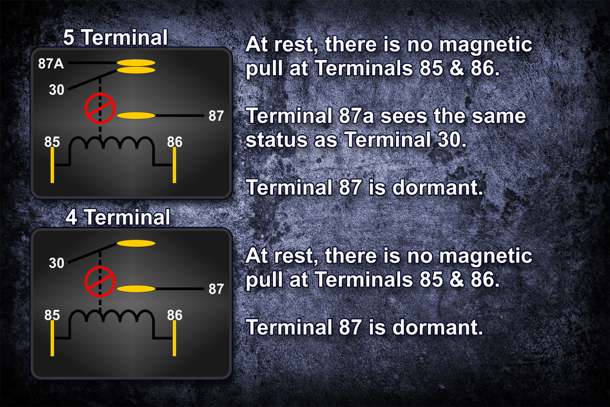
While it may look complex, it’s really a simple switching circuit to control your cooling fans. You won’t need to be an expert to install a relay kit, but it does help to have the proper tools, and a little bit of know how.
One sure fire way to make sure that your wiring is connected properly is to test your relay system, much in the same manner that we would ask if you call for assistance:
- Turn the ignition key to the ‘on’ or ‘run’ position
- Connect a jumper wire from the top of the thermal switch to a sold ground connection either on the engine or to the chassis.
- You should hear the relay(s) click, and the fans should come on. This won’t harm your electrical or your relay kit providing that you have wired it properly.
- Disconnect the jumper wire from the thermal switch, and your fan(s) should turn off.
We hope this helps to provide a better understanding of how your relays function. The video below provides a more in-depth look at how our Electric Cooling Fan Relays work.